Liquid reductant system and method for operation of the liquid reductant system

a liquid reductant and liquid technology, applied in the field of liquid reductant system and liquid reductant solution heating, can solve the problems of reducing fuel economy, increasing the cost of heating and freezing components of the urea storage tank and the reductant injection system, and the inability of the injection system to deliver urea to the injector, etc., to achieve the effect of reducing the size and/or operating temperature range at which the thermosyphon function can be performed, reducing the freezing point temperature of the liquid redu

Active Publication Date: 2013-08-15
FORD GLOBAL TECH LLC
View PDF7 Cites 23 Cited by
  • Summary
  • Abstract
  • Description
  • Claims
  • Application Information

AI Technical Summary

Benefits of technology

[0004]At ambient temperatures of less than −11° C., the aqueous urea solution (comprising 32.5% urea and 67.5% water) may freeze in the on board urea storage tank. Thus, a pick-up tube of the injection system may not be able to deliver urea to the injector for delivery to exhaust gas and NOx reduction. In one approach, the urea storage tank includes an electric heating system to warm the frozen urea. Further, components of the urea storage tank and reductant injection system may have a freeze-safe design to assure functionality and survivability of the injection system over multiple freeze / thaw cycles.
[0005]The inventors of the present application have recognized a problem in the above solutions. First, there may be increased cost associated with the heating and freeze-safe components for the urea storage tank and reductant injection system. Second, fuel economy may be decreased by using energy produced by the vehicle to heat the entire urea tank, and such heating may take an extended duration, thus reducing the amount of exhaust gasses that can be treated catalytically with the reductant, and thus increasing exhaust emissions overall.
[0007]In this way, waste heat from the exhaust system can be used to passively heat the reductant solution in the storage tank via the thermosyphon. In some examples, the thermosyphon is a closed-loop thermosyphon. Thus, in such an example, the thermosyphon does not need an outside power source or controller to operate although such components could be used, if desired. As a result, the reductant solution is heated without decreasing the fuel economy by using energy produced by combustion to heat the storage tank.
[0008]Additionally, in some examples the reductant solution may include ethanol. By including ethanol in the reductant solution, a freezing point temperature of the liquid reductant may be reduced. As such, the occurrences of reductant freezing may be reduced and / or the size and / or operating temperature range at which thermosyphon functions can be decreased.

Problems solved by technology

Thus, a pick-up tube of the injection system may not be able to deliver urea to the injector for delivery to exhaust gas and NOx reduction.
First, there may be increased cost associated with the heating and freeze-safe components for the urea storage tank and reductant injection system.
Second, fuel economy may be decreased by using energy produced by the vehicle to heat the entire urea tank, and such heating may take an extended duration, thus reducing the amount of exhaust gasses that can be treated catalytically with the reductant, and thus increasing exhaust emissions overall.

Method used


Image

  • Liquid reductant system and method for operation of the liquid reductant system
  • Liquid reductant system and method for operation of the liquid reductant system
  • Liquid reductant system and method for operation of the liquid reductant system

Examples


Embodiment Construction

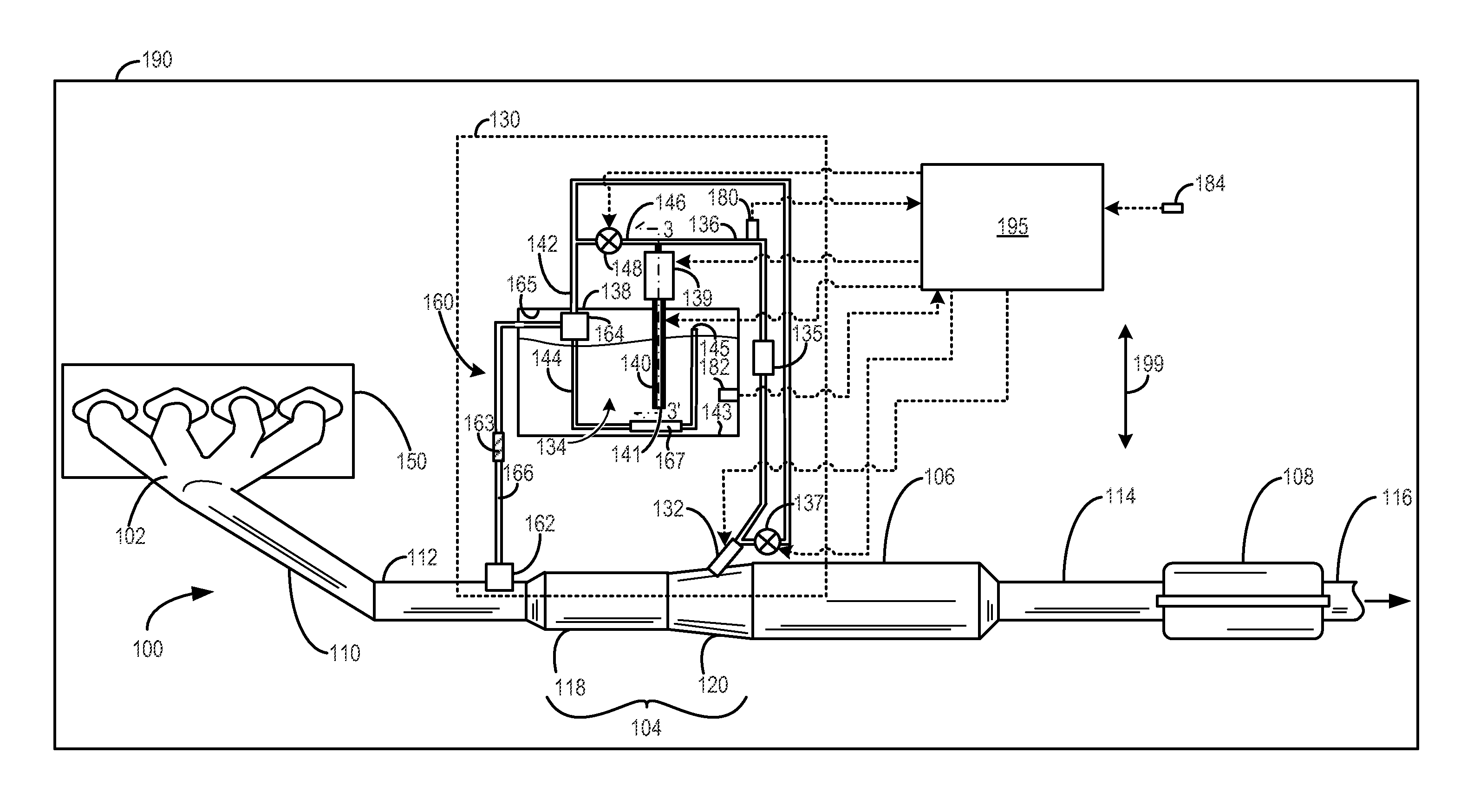
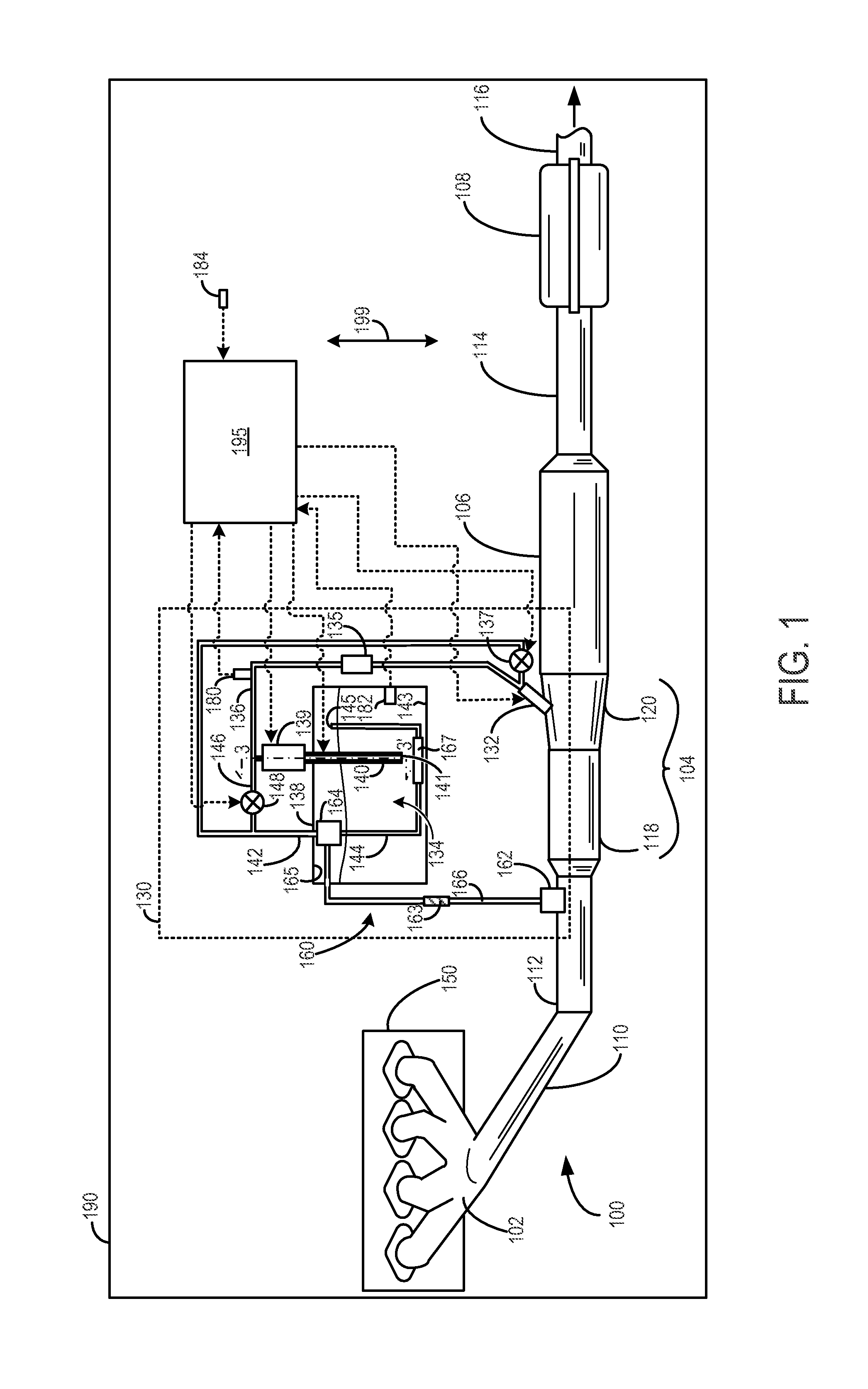
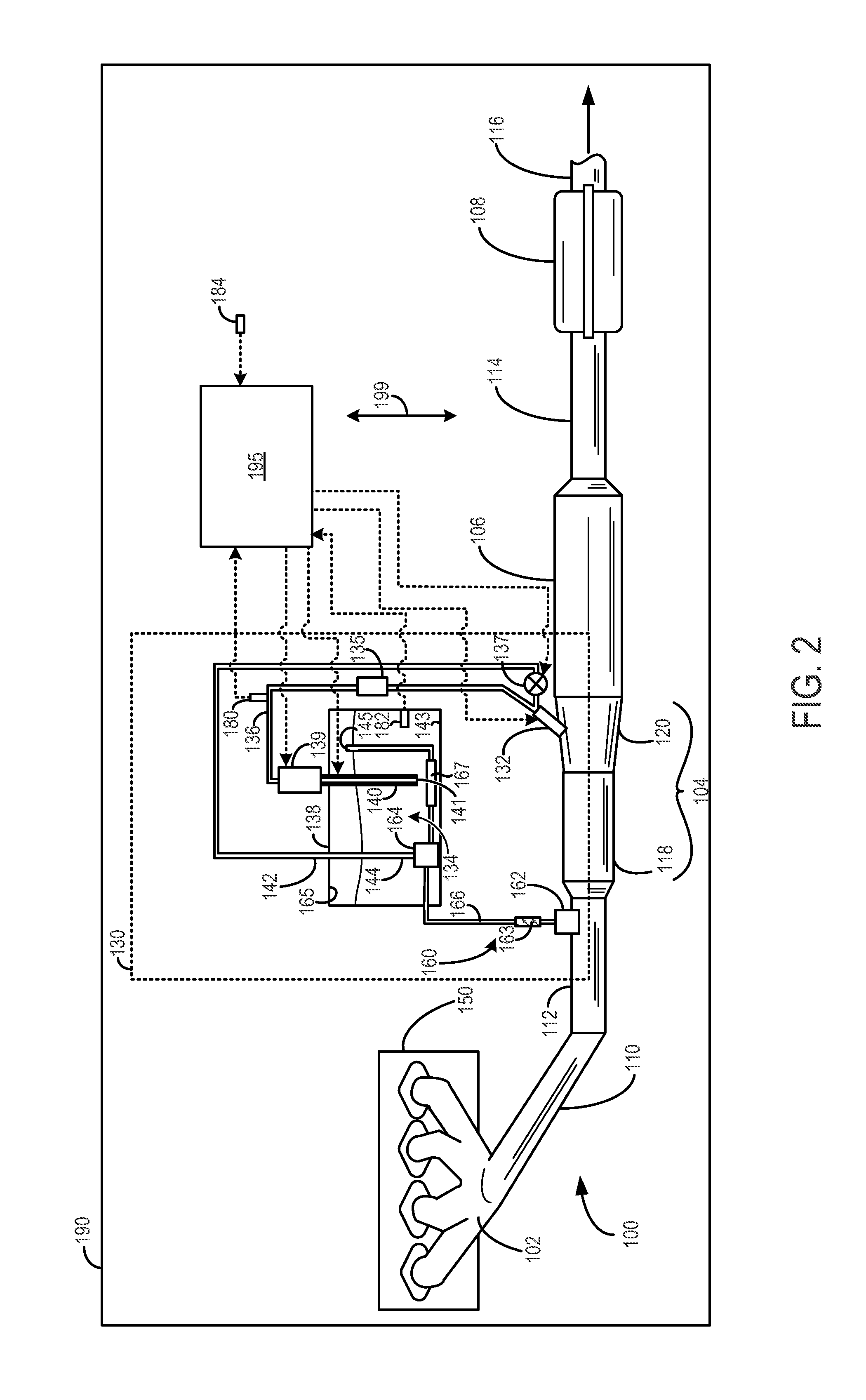
[0014]Embodiments of an exhaust system and a liquid reductant injection system for use with an aqueous urea and ethanol solution are disclosed herein. Such a liquid reductant injection system may be utilized for exhaust gas treatment by NOx reduction in various ambient temperature conditions. More specifically, the reductant injection system may be used to treat exhaust gas in ambient temperatures below a normal freezing temperature of aqueous urea. In particular, the reductant injection system may include a thermosyphon which passively transfers heat from exhaust gas to stored reductant, as described in more detail hereafter. Consequently, the reductant solution is heated without decreasing the fuel economy by using energy produced by combustion to heat the storage tank.

[0015]FIG. 1 includes an example exhaust system for a vehicle with an engine including a reductant injection system. FIG. 2 shows another embodiment of an exhaust system. FIG. 3 shows a cross section of a heated pic...


PUM


Abstract

A liquid reductant injection system is provided. The liquid reductant injection system includes a storage tank housing a reductant solution, a return conduit extending into the storage tank, the return conduit including an outlet positioned in the storage tank, and a thermosyphon comprising an evaporator coupled to an exhaust conduit and in fluidic communication with a condenser coupled to a portion of the return conduit inside the storage tank, the condenser positioned vertically above the evaporator.

Description

CROSS REFERENCE TO RELATED APPLICATION[0001]The present application claims the benefit of and priority to U.S. Provisional Patent Application No. 61 / 596,846, filed on Feb. 9, 2012, entitled LIQUID REDUCTANT SYSTEM AND METHOD FOR OPERATION OF THE LIQUID REDUCTANT SYSTEM, the content of which is incorporated herein by reference for all purposes.TECHNICAL FIELD[0002]The present application relates to a system and a method for heating a reductant solution in a storage tank of an exhaust treatment system of a vehicle.BACKGROUND AND SUMMARY[0003]Many vehicles utilize catalysts in exhaust systems to reduce emission. In lean exhaust conditions, such as with regard to diesel exhaust or other lean burning conditions, a catalyst may utilize reductant other than burnt fuel. One such aftertreatment device is a Selective Catalytic Reduction (SCR) system, which uses a catalyst to convert NOx to nitrogen and water. A urea-based SCR catalyst may use gaseous ammonia as the active NOx reducing agent, ...

Claims


Application Information

Patent Timeline
Patent Type & Authority Applications(United States)
IPC IPC(8): F01N3/24
CPCF01N3/2066F01N2240/22F01N2610/02Y02T10/24F01N2610/1473F01N2900/1811F01N2610/14Y02T10/12
Inventor LEVIN, MICHAELSHAIKH, FURQAN ZAFARMCCARTHY, THOMAS A.
Owner FORD GLOBAL TECH LLC
Why Eureka
Try Eureka