Method and systems for operating a wind turbine using dynamic braking in response to a grid event

a technology of dynamic braking and wind turbine, which is applied in the direction of electric generator control, machines/engines, mechanical equipment, etc., can solve problems such as system controllability and/or equipment malfunction, potential damage to the electrical system of the wind turbine, and disturbances on the dc bus voltag

Active Publication Date: 2014-03-04
GENERAL ELECTRIC CO
View PDF52 Cites 51 Cited by
  • Summary
  • Abstract
  • Description
  • Claims
  • Application Information

AI Technical Summary

Problems solved by technology

However, as the length of transmission line feeder to the DFIG wind turbine system is increased, response to grid transients and grid disturbances causes oscillations of power into and out of the converter which create disturbances on the DC bus voltage in the converter.
Such power oscillations may, over time, lead to degradation of system controllability and / or equipment malfunctions.
The above-described events pose a potential for damage to the wind turbine electrical system due to high voltages within that system that exceed equipment capability.
However, when the grid becomes open-circuited after clearing the fault, then it is desirable that the wind turbines continue operating without damage and eventually shut down based on inability to transfer power.
Generally; however, such a system does not allow the wind turbine system to recover fast enough to meet the some grid code standards and / or regulations.
With existing control methods, as longer transmission line lengths are desired, possibly coupled with larger grid voltage transients, the voltage overshoots on the DC bus voltage in the converter may reach a level to damage the components in the converter.

Method used


Image

  • Method and systems for operating a wind turbine using dynamic braking in response to a grid event
  • Method and systems for operating a wind turbine using dynamic braking in response to a grid event
  • Method and systems for operating a wind turbine using dynamic braking in response to a grid event

Examples


Embodiment Construction

[0017]Before the present methods and systems are disclosed and described, it is to be understood that the methods and systems are not limited to specific synthetic methods, specific components, or to particular compositions. It is also to be understood that the terminology used herein is for describing particular embodiments only and is not intended to be limiting.

[0018]As used in the specification and the appended claims, the singular forms “a,”“an” and “the” include plural referents unless the context clearly dictates otherwise. Ranges may be expressed herein as from “about” one particular value, and / or to “about” another particular value. When such a range is expressed, another embodiment includes from the one particular value and / or to the other particular value. Similarly, when values are expressed as approximations, by use of the antecedent “about,” it will be understood that the particular value forms another embodiment. It will be further understood that the endpoints of eac...


PUM


Abstract

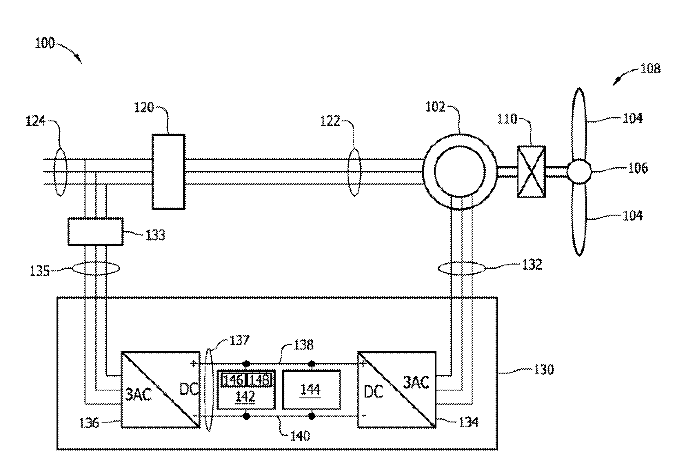
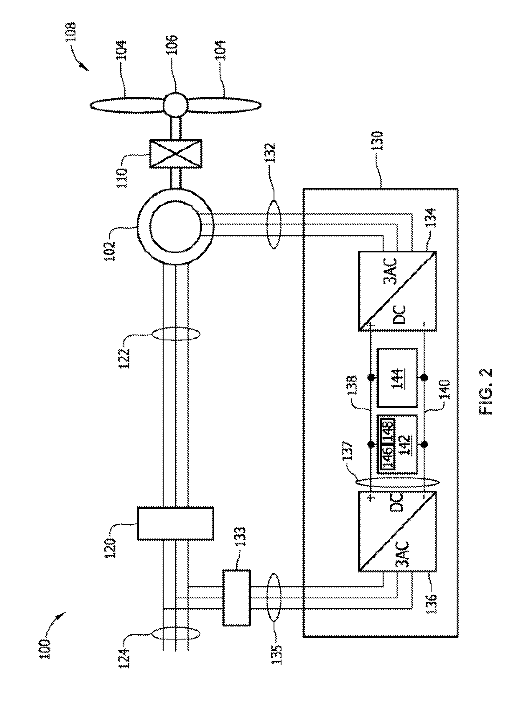
A method and system for dissipating energy in a direct current (dc) bus of a doubly-fed induction generator (DFIG) converter during a grid event is described. In one aspect, the method comprises monitoring operating conditions of an electrical system, the electrical system comprising at least a DFIG generator and a line side converter and a rotor side converter connected by a dc bus having a dynamic brake connected thereto; detecting an overvoltage on the dc bus or a condition indicative of an overvoltage on the dc link is detected, the overvoltage on the dc bus or condition indicative of the overvoltage caused by a grid event; and causing energy in the dc link to be dissipated using the dynamic brake.

Description

BACKGROUND[0001]The field of the disclosure relates generally to methods and systems for use in controlling operation of a wind turbine, and more specifically, to controlling the operation of a wind turbine using dynamic braking in response to an islanding event.[0002]Generally, wind turbine systems regulate a positive sequence voltage with a closed-loop current regulation scheme that minimizes negative sequence current. Such systems work well and are known to be reliable at constant output power levels. However, as the length of transmission line feeder to the DFIG wind turbine system is increased, response to grid transients and grid disturbances causes oscillations of power into and out of the converter which create disturbances on the DC bus voltage in the converter. Such power oscillations may, over time, lead to degradation of system controllability and / or equipment malfunctions. In some grid faults, upon clearing, the wind plant is left with no remaining connection to the gri...

Claims


Application Information

Patent Timeline
Patent Type & Authority Patents(United States)
IPC IPC(8): H02P9/04F03D9/00
CPCY02E10/723Y02E10/725F03D7/0244F05B2260/90F05B2270/107H02J2300/28H02J3/381Y02E10/72Y02E10/76
Inventor WAGONER, ROBERT GREGORYRITTER, ALLEN MICHAELLARSEN, EINAR VAUGHNKLODOWSKI, ANTHONY MICHAELBARKER, SIDNEY ALLEN
Owner GENERAL ELECTRIC CO
Why Eureka
Try Eureka