Electronic assembly having stressable contact bridge with fuse function

a technology of stress-free contact bridge and fuse function, which is applied in the direction of printed circuit aspects, non-printed jumper connection addition, high current circuit adaptation, etc., can solve the problems of assembly power dissipation and total destruction of circuit boards, and achieve quick and abrupt interruption, the effect of avoiding the increase of power dissipation in the assembly

Active Publication Date: 2014-03-04
CONTI TEMIC MICROELECTRONIC GMBH
View PDF39 Cites 46 Cited by
  • Summary
  • Abstract
  • Description
  • Claims
  • Application Information

AI Technical Summary

Benefits of technology

[0004]Therefore, an underlying object of the invention is to set forth an electronic assembly of the abovementioned type, which is secured to a high degree by simple means against a possible occurrence of high power dissipation.
[0011]For an especially reliable safety or fuse function, the electronic assembly is advantageously designed in such a manner so that the current supply to the circuit board or to individual components is interrupted in a targeted manner upon the occurrence of an unexpected temperature increase, because thereby the power dissipation can be reduced especially effectively and quickly. In order to ensure this, at least one of the contact bridges is advantageously mounted on a supply conductor strip through which a current feed or supply to the components mounted on the circuit board is carried out.
[0014]Through the provision of spring-loaded contact bridges for providing electrical connections between conductor strips and / or components on the circuit board, the invention achieves the advantage that the electrical connection produced by the contact bridge is quickly and abruptly interruptable upon the occurrence of an increased temperature, which causes a melting or softening of the soldered connection location of the contact bridge to the circuit board, and therewith releases the contact bridge which then springs open due to its springy pre-stress and thereby interrupts the electrical connection. Thereby the energy supply to the circuit board in total or to individual components can be interrupted reliably, abruptly and quickly on the assembly, as soon as an unexpected temperature increase occurs. Thereby resultant damages due to increased power dissipation in the assembly are surely avoided.

Problems solved by technology

Depending on the application purpose, with such assemblies an unacceptably high loss power dissipation could arise in the assembly due to faulty components such as switching transistors for example, due to circuit board short circuits, or due to water penetration.
In severe cases, this power dissipation could lead to the total destruction of the circuit board.

Method used


Image

  • Electronic assembly having stressable contact bridge with fuse function
  • Electronic assembly having stressable contact bridge with fuse function
  • Electronic assembly having stressable contact bridge with fuse function

Examples


second embodiment

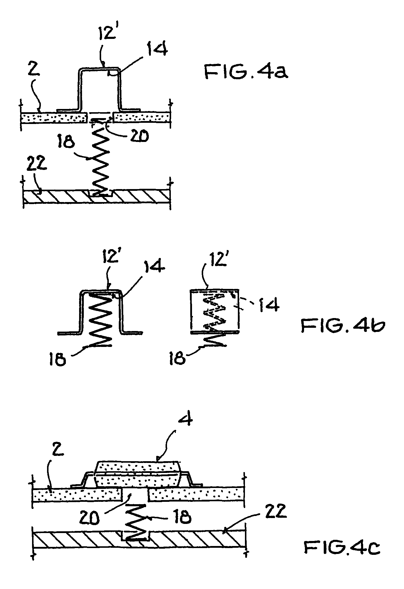
[0029]a contact bridge 12′ is similar in its embodiment or design to the first contact bridge 12, whereby in this case however, the compression spring 18 is guided or passed through an allocated hole 20 in the circuit board 2. Thereby the compression spring 18 can be installed so as to stress the contact bridge 12′ after the contact bridge 12′ has been solder-mounted in an unstressed condition.

[0030]The third alternative embodiment of the contact bridge 12″ is, in contrast, embodied in a one-piece manner so that the contact bridge 12″ is itself springy and stressable without use of a separate compression spring. In that regard, the contact bridge 12″ is formed of a springy base body 14 for example made of spring steel or any elastically deformable metal, which can be given a suitable internal pre-stress through its form or structure. In that regard, the contact bridge 12″ is suitably formed and pre-stressed already in the fabrication step, and is mounted under or with this pre-stres...

fourth embodiment

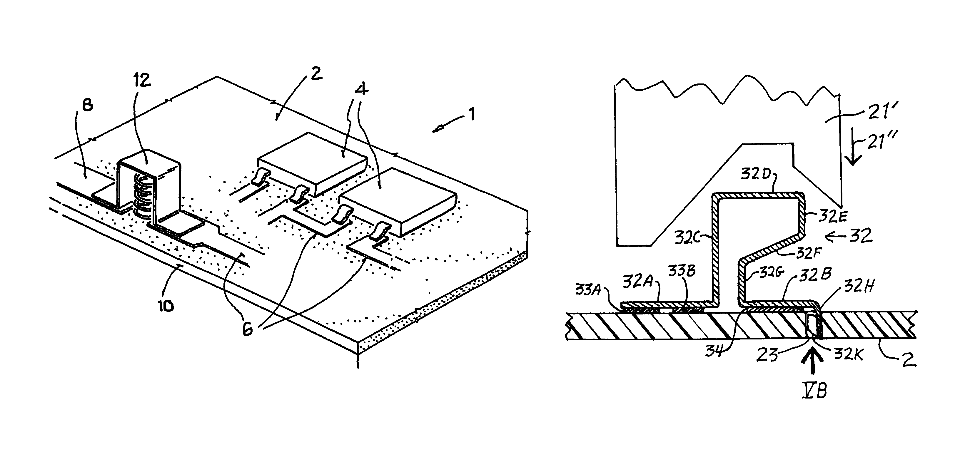
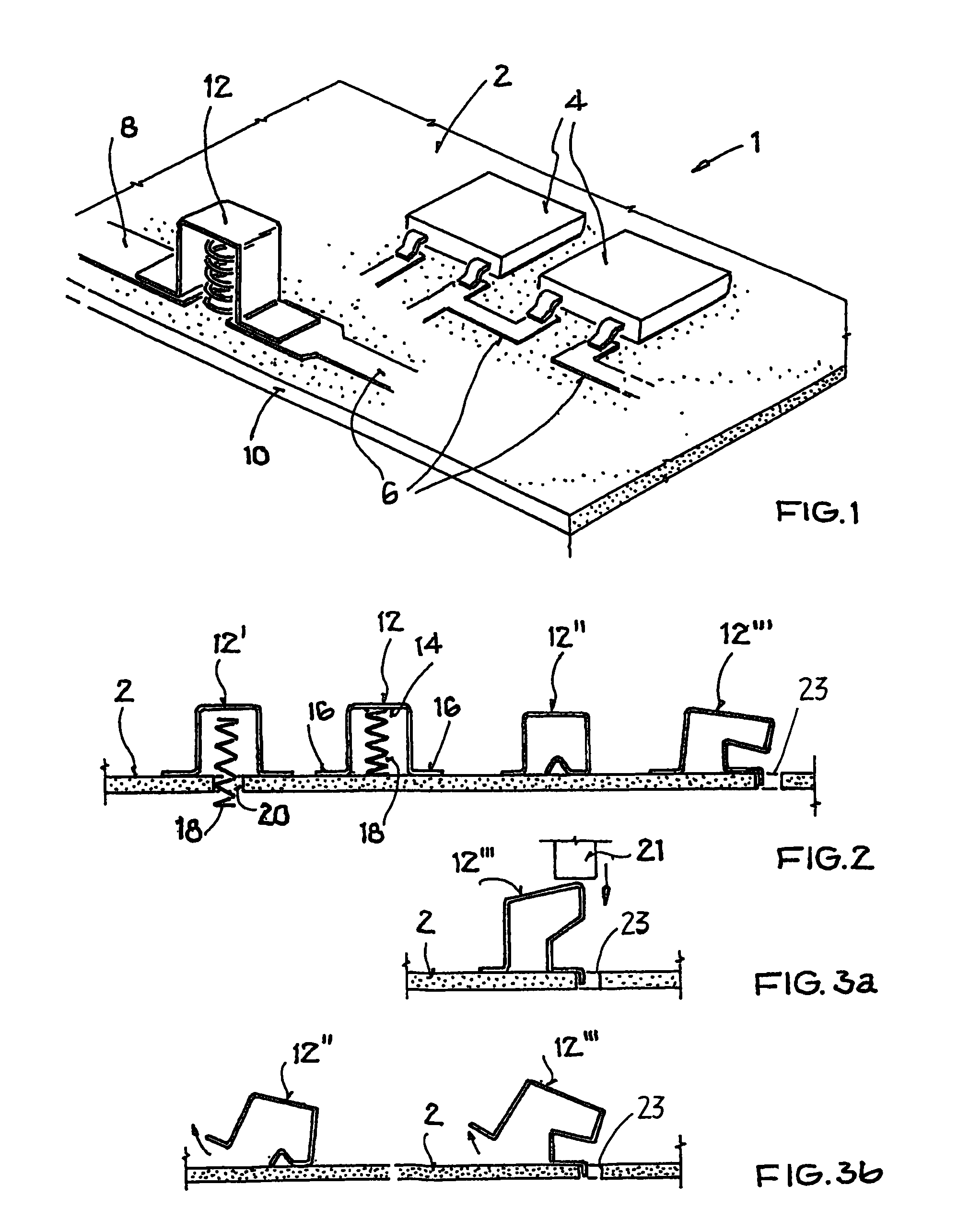
[0031]In contrast, a contact bridge 12′″, which is similarly embodied in one-piece without further components and without an external compression spring, is initially fabricated in an unstressed or pre-stress-less manner. The unstressed contact bridge 12′″ can thus be solder-mounted in an especially simple manner also with SMD technology, without requiring any special support or maintaining of a special stressed configuration. Subsequently, i.e. after it is mounted, the contact bridge 12′″ is deformed for producing the desired spring loading or pre-stress, whereby for example a suitably positioned pressing die or stamp 21 can be utilized for deforming the contact bridge 12′″ from an unstressed configuration to a stressed configuration as can be seen by comparing FIG. 3a with FIG. 2.

[0032]Further details of the variants of the contact bridge 12 are shown in FIGS. 3a, 3b and 4. FIG. 3a shows the fourth contact bridge 12′″ in its initial unstressed configuration directly before or dire...


PUM


Abstract

An electronic circuit includes a conductor path on a circuit board, and at least one SMD component, electronic component and / or electromechanical component mounted on the circuit board and connected to the conductor path. A circuit connection is established via a soldered joint and a spring-loaded or stressed springy contact bridge that provides fuse protection. In the event of excessive power dissipation or high temperature, the soldered joint melts or softens and the contact bridge springs open to interrupt the circuit.

Description

CROSS-REFERENCE TO RELATED APPLICATIONS[0001]This application is a Continuation-In-Part under 35 USC 120 of U.S. application Ser. No. 11 / 886,755 filed on Sep. 19, 2007, which is a US National Stage Application under 35 USC 371 of PCT International Application PCT / DE2006 / 000550 filed on Mar. 28, 2006. Through those prior applications, this application is also based on and claims the foreign priority under 35 USC 119 of German Patent Application 10 2005 014 601.5 filed on Mar. 31, 2005. The entire disclosure of each one of the above mentioned prior applications is incorporated herein by reference.FIELD OF THE INVENTION[0002]The invention relates to a stressable contact bridge with a fuse function for an electronic assembly with a circuit board that is provided with conductor strips or paths and, for forming an electronic circuit, is equipped with a number of SMD (“Surface Mounted Device”) components and / or further electronic and / or electromechanical elements while using a suitable sol...

Claims


Application Information

Patent Timeline
Patent Type & Authority Patents(United States)
IPC IPC(8): H01H85/36H01H37/76
CPCH05K3/341H01H37/761H05K2201/10181H05K1/0201H05K2201/10265H05K2201/0311H05K1/0263H05K3/222H05K3/3415
Inventor SCHLENKER, ROBERTONAGEL, MICHAELMARTIN, JUERGEN
Owner CONTI TEMIC MICROELECTRONIC GMBH
Why Eureka
Try Eureka