Domestic appliance with an open air duct

a technology of open air ducts and domestic appliances, applied in the direction of liquid fuel engine components, non-progressive movement drying machines, non-positive displacement fluid engines, etc., can solve the problem of components permeating outwards, and achieve the effect of reducing nois

Inactive Publication Date: 2014-03-11
BOSCH SIEMENS HAUSGERATE GMBH
View PDF34 Cites 10 Cited by
  • Summary
  • Abstract
  • Description
  • Claims
  • Application Information

AI Technical Summary

Benefits of technology

[0005]It is an object of an exemplary embodiment of the present invention to provide a domestic appliance, which enables a noise reduction in the surroundings of the domestic appliance.
[0007]A domestic appliance includes an open air duct, with a flow cross-section adjusting facility for adjusting a flow cross-section of the air duct being arranged in the air duct. The air duct can comprise an essentially arbitrary cross-sectional shape which can also change in terms of its course. A passage of sound waves through the flow cross-section adjusting facility is complicated by a cross-section which can be minimized for the cooling so that an interference noise emanating from the domestic appliance can be reduced. There is thus one embodiment such that the flow cross-section can be adjusted to a flow cross-section which can be minimized or is minimal for a predetermined or required cooling power.
[0009]The flow cross-section adjusting facility preferably comprises blades, with the blades being rotatably mounted in the air duct for noise damping purposes, in particular at varying angles at right angles to the cross-section of the air duct. A partial or complete closure of such blades enables noise radiating from noise-generating components, such as an engine or compressor, to be clearly reduced by means of the cooling air duct. Compared with other closing elements, the blades enable particularly high noise damping and a low sound level fluctuation.
[0013]For particularly simple realization of a variable adjustment of the flow cross-section, this can be adjustably embodied by means of a flow speed of the air. To this end, blades can be used which can be angled particularly easily and in a defined fashion by means of the cooling air speed.

Problems solved by technology

The disadvantage of such an arrangement in conjunction with noise-generating components such as engines and compressors within the domestic appliance is that noises developing as a result of these components permeate outwards across the ventilation opening between the blades into the area outside of the domestic appliance.

Method used


Image

  • Domestic appliance with an open air duct
  • Domestic appliance with an open air duct
  • Domestic appliance with an open air duct

Examples


Embodiment Construction

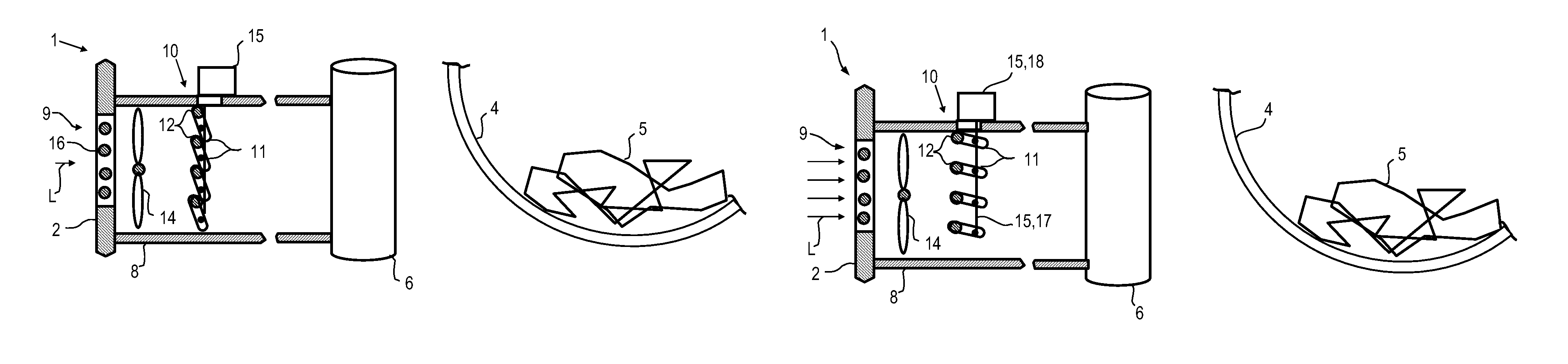
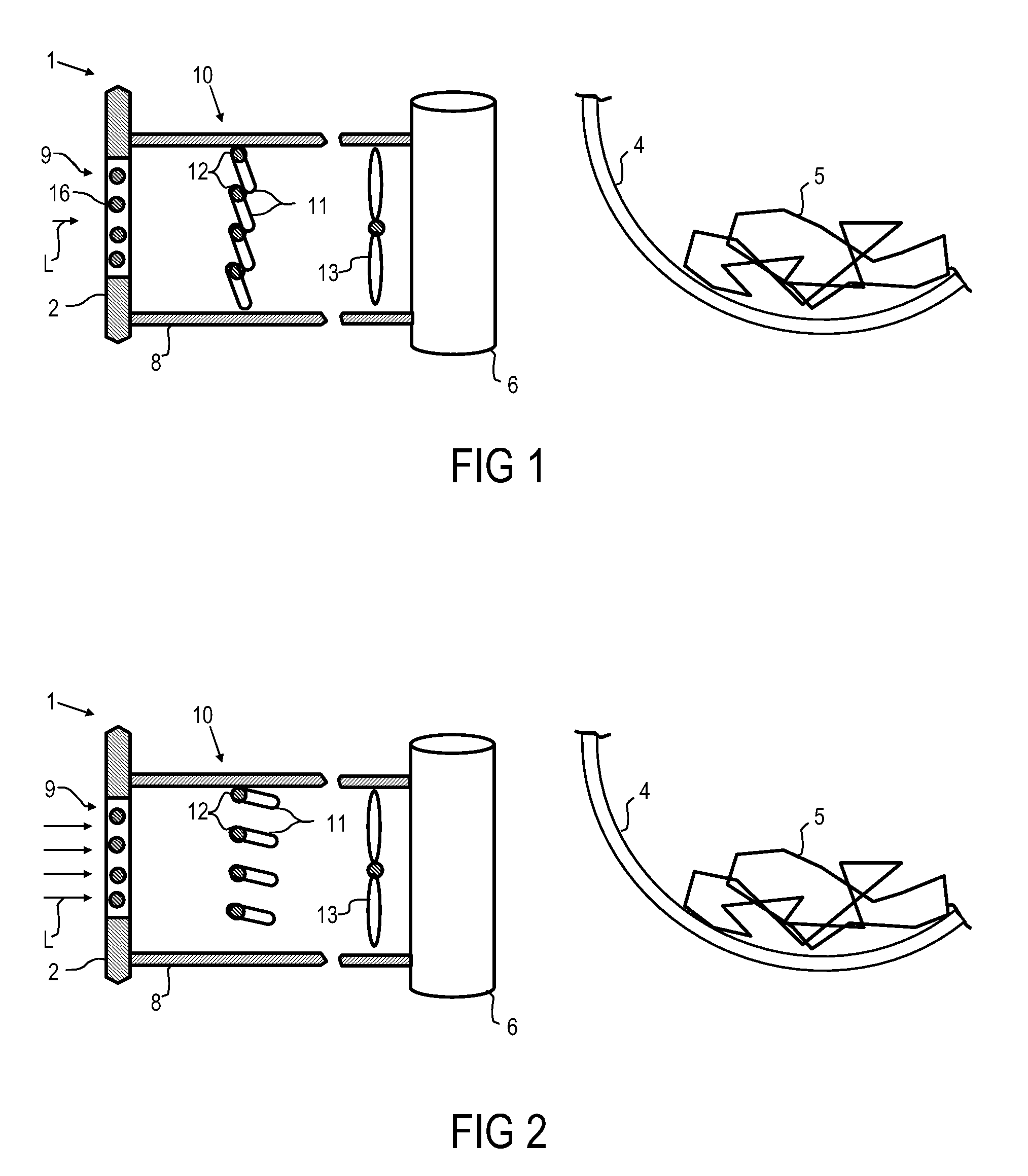
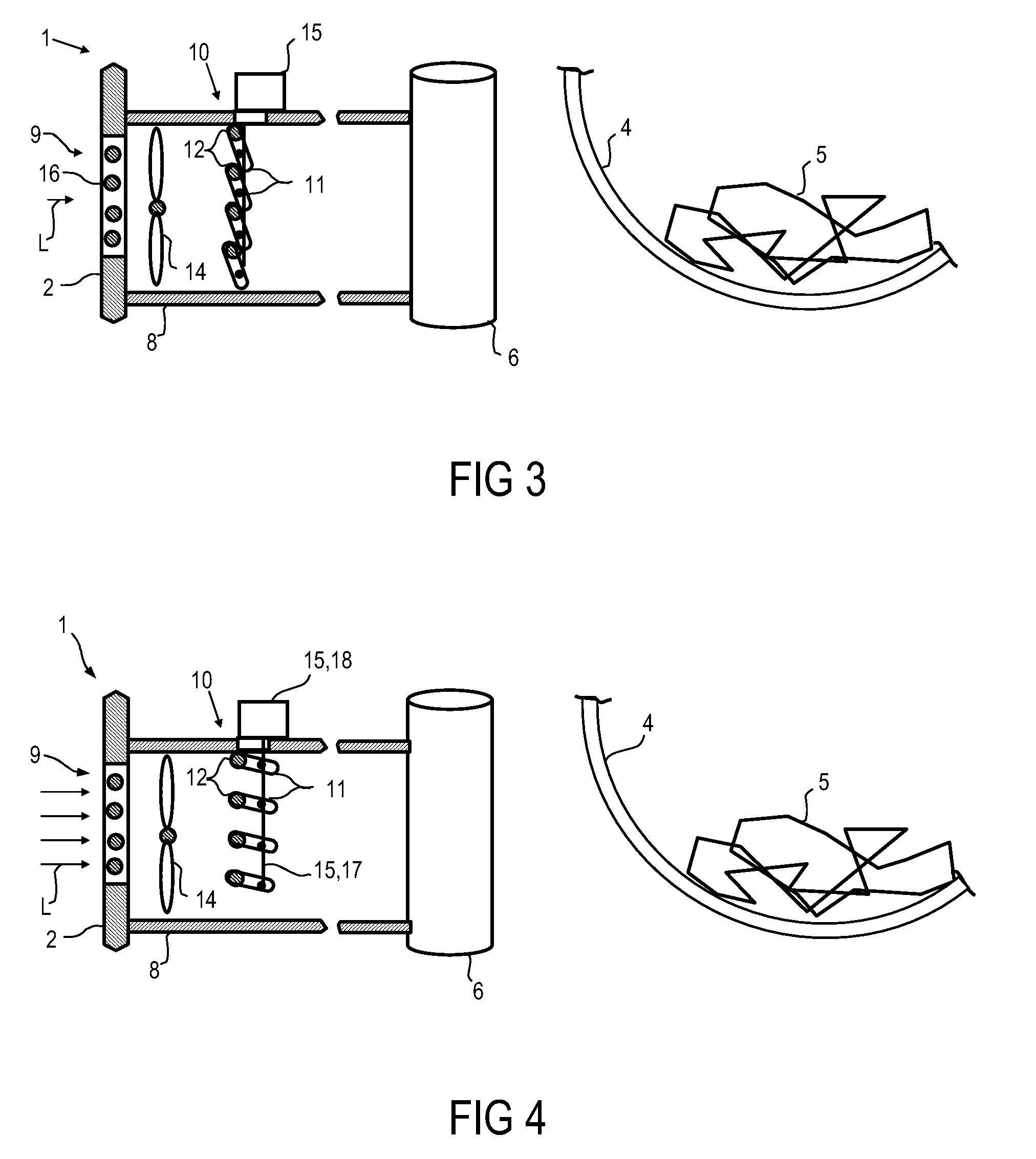
[0023]FIG. 1 shows individual components of a domestic appliance 1. The exemplary domestic appliance 1 is a tumble dryer with a surrounding housing 2, which comprises a drum 4 for receiving laundry 5 to be dried. An air intake opening 9 is embodied in the housing 2, in order to be able to supply cooling air L to a compressor 6 of a heat pump. The air intake opening 9 is provided with a protective grid 16 for aesthetic and safety reasons. An air duct 8 leads from the air intake opening 9 to a compressor 6 to be cooled of a heat pump. To be able to control an intensity of an air flow of the process air L, a fan 13 is provided, which is arranged upstream of the compressor 6 in the air duct 8. With the fan 13, cooling air L is correspondingly taken in from outside through the air intake opening 9. A flow cross-section adjusting facility 10 is arranged in the air duct 8, in order to prevent noises generated by the compressor 6 from escaping outwards. The flow cross-section adjusting faci...


PUM


Abstract

A domestic appliance includes an open air duct and a flow cross-section adjuster in the air duct for adjusting a flow cross-section of the air duct. The flow cross-section adjuster includes rotatably mounted blades for noise dampening purpose. The air duct and the flow cross-section adjuster are in a cooling air inflow region relative to a heat exchanger or a compressor of the domestic appliance.

Description

BACKGROUND OF THE INVENTION[0001]The invention relates to a domestic appliance with an open air duct. More particularly, the invention relates to a domestic appliances with an air duct which opens toward the surroundings of the domestic appliance and is therefore not closed.[0002]Domestic appliances, for instance tumble dryers, which comprise a housing opening, through which air from outside of the domestic appliance is taken into the interior thereof, are generally known. Input air is conveyed as cooling air through an air duct mounted on a corresponding housing opening to at least one component to be cooled. The disadvantage of such an arrangement in conjunction with noise-generating components such as engines and compressors within the domestic appliance is that noises developing as a result of these components permeate outwards across the ventilation opening between the blades into the area outside of the domestic appliance.[0003]EP 1 813 712 A1 relates to a dryer with a drum fo...

Claims


Application Information

Patent Timeline
Patent Type & Authority Patents(United States)
IPC IPC(8): F26B3/04
CPCD06F58/28D06F58/20
Inventor EDIGER, RAINERNAWROT, THOMASNUHSE, WERNER
Owner BOSCH SIEMENS HAUSGERATE GMBH
Why Eureka
Try Eureka