Turbo fan and air conditioner with turbo fan

a technology of turbofans and air conditioners, which is applied in the direction of marine propulsion, lighting and heating apparatus, and vessel construction, etc., can solve the problems of reducing the airflow of turbofans, and achieve the effect of increasing the contact area with air without increasing the length of the blade, reducing the amount of airflow, and increasing the positive pressure of the blad

Inactive Publication Date: 2014-03-11
LG ELECTRONICS INC
View PDF8 Cites 8 Cited by
  • Summary
  • Abstract
  • Description
  • Claims
  • Application Information

AI Technical Summary

Benefits of technology

[0009]An advantage of the present invention is to provide a turbo fan that may secure a enough amount of airflow and increase positive pressure in the blade of the fan.
[0010]Another advantage of the present invention is to provide a turbo fan that may increase a contact area with air without increasing the length of a blade.

Problems solved by technology

As a result, there happens a problem that the airflow blown by the turbo fan is reduced.

Method used


Image

  • Turbo fan and air conditioner with turbo fan
  • Turbo fan and air conditioner with turbo fan
  • Turbo fan and air conditioner with turbo fan

Examples


Embodiment Construction

[0027]Reference will now be made in detail to embodiments of the present invention, examples of which is illustrated in the accompanying drawings. Wherever possible, the same reference numbers will be used throughout the drawings to refer to the same or like parts.

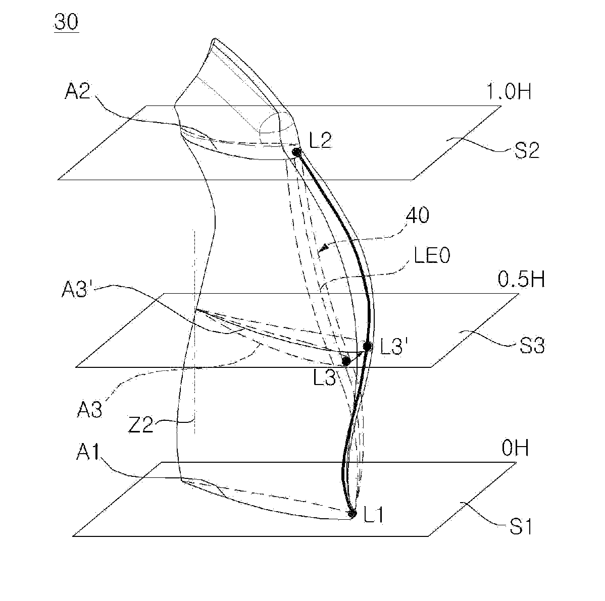
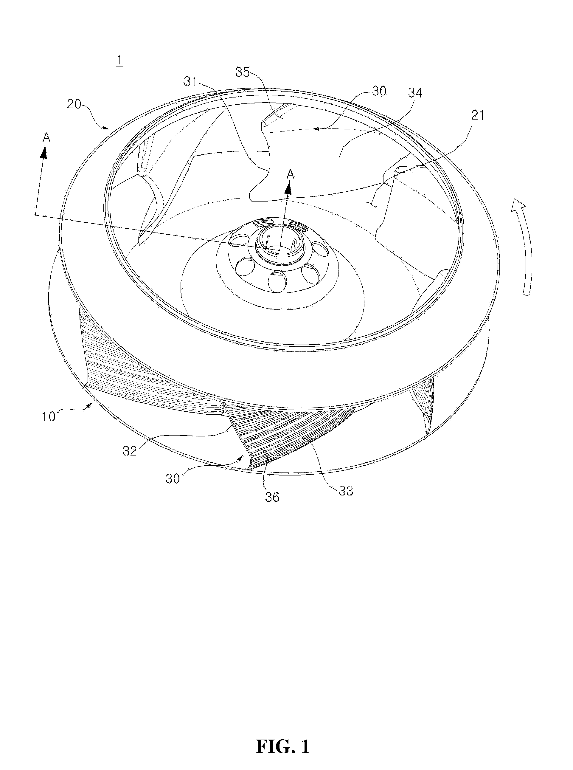
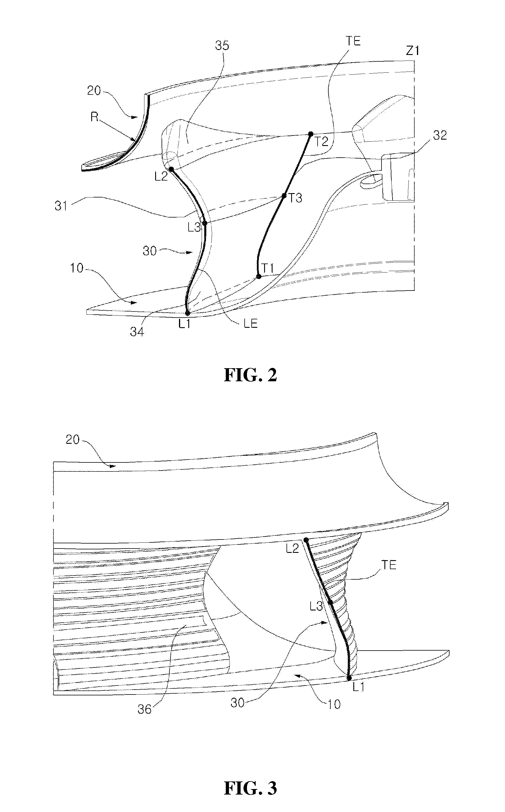
[0028]FIG. 1 is a perspective view illustrating a turbo fan according to an embodiment of the present invention. FIG. 2 is a view taken along line A-A of FIG. 1. FIG. 3 is a partially magnified view illustrating a trailing edge of a blade shown in FIG. 1. FIG. 4 is perspective view illustrating a blade of FIG. 1. FIG. 5 is a perspective view illustrating a blade of FIG. 1, comparing the blade with a blade of a comparative embodiment. FIG. 6 is a projective view illustrating a sectional shape of a blade at each parallel surface of FIG. 4.

[0029]Referring to FIGS. 1 through 3, a turbo fan 1 may include a main plate 10 rotated by a motor providing rotational force, a plurality of blades 30 having ends connected to the main pla...


PUM


Abstract

A turbo fan includes a main plate for rotation in a rotational direction about a rotational axis and a plurality of blades arranged at intervals around the rotational axis of the main plate. At least one blade includes: a first blade section having a leading end and a trailing end; a second blade section having a leading end and a trailing end, wherein the first blade section is between the main plate and the second blade section; and a third blade section having a leading end and a trailing end, wherein the third blade section is between the first blade section and the second blade section.

Description

CROSS-REFERENCE TO RELATED APPLICATION[0001]This application claims priority from Korean Patent Application No. 10-2010-0086156, filed on Sep. 2, 2010 in the Korean Intellectual Property Office, the entire contents of which are incorporated herein by reference for all purposes as if fully set forth herein.BACKGROUND OF THE INVENTION[0002]1. Field of the Invention[0003]Exemplary embodiments of the present invention relate to a turbo fan and an air conditioner.[0004]2. Description of the Related Art[0005]Generally, air-blowing fans are widely used for forcibly blowing air by rotational force of a rotor or an impeller in refrigerators, air conditioners, and cleaners. Particularly, air-blowing fans are divided into axial flow fans, sirocco fans, and turbo fans according to how air is suctioned and discharged and their configuration.[0006]Turbo fans adopt a method of suctioning air in an axial direction of the fan and discharging the air in a radial direction through spaces between the b...

Claims


Application Information

Patent Timeline
Patent Type & Authority Patents(United States)
IPC IPC(8): F04D29/38
CPCF04D29/281F04D29/30F04D29/282
Inventor HAN, SUNGWONCHOI, INHOKIM, KYUNGHWANKIM, KIDONG
Owner LG ELECTRONICS INC
Why Eureka
Try Eureka