
Hydraulic system with supplement pump

a technology of hydraulic system and pump, applied in the direction of pumps, mechanical equipment, liquid fuel engines, etc., can solve the problems of inability to discharge high pressure fluid, particularly bad dumping of high pressure fluid, and high loss, and achieve energy-efficient hydraulic fluid flow and low cost.

Active Publication Date: 2014-03-11
DANFOSS PAUER SOLYUSHENS APS
View PDF53 Cites 17 Cited by
  • Summary
  • Abstract
  • Description
  • Claims
  • Application Information

AI Technical Summary

Benefits of technology

[0011]The object of the invention is therefore to provide a hydraulic system, which is able to provide an energy-efficient hydraulic fluid flow at low cost.
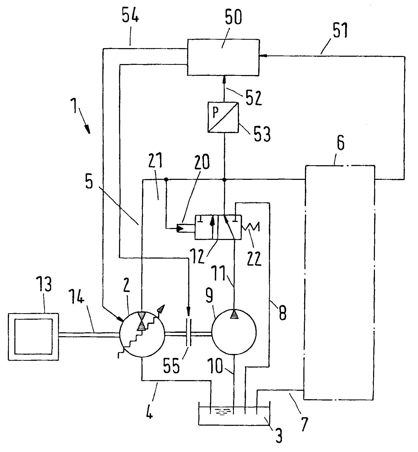
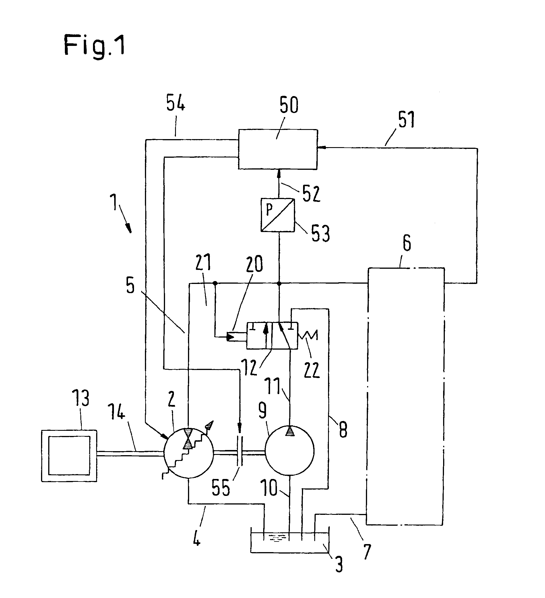
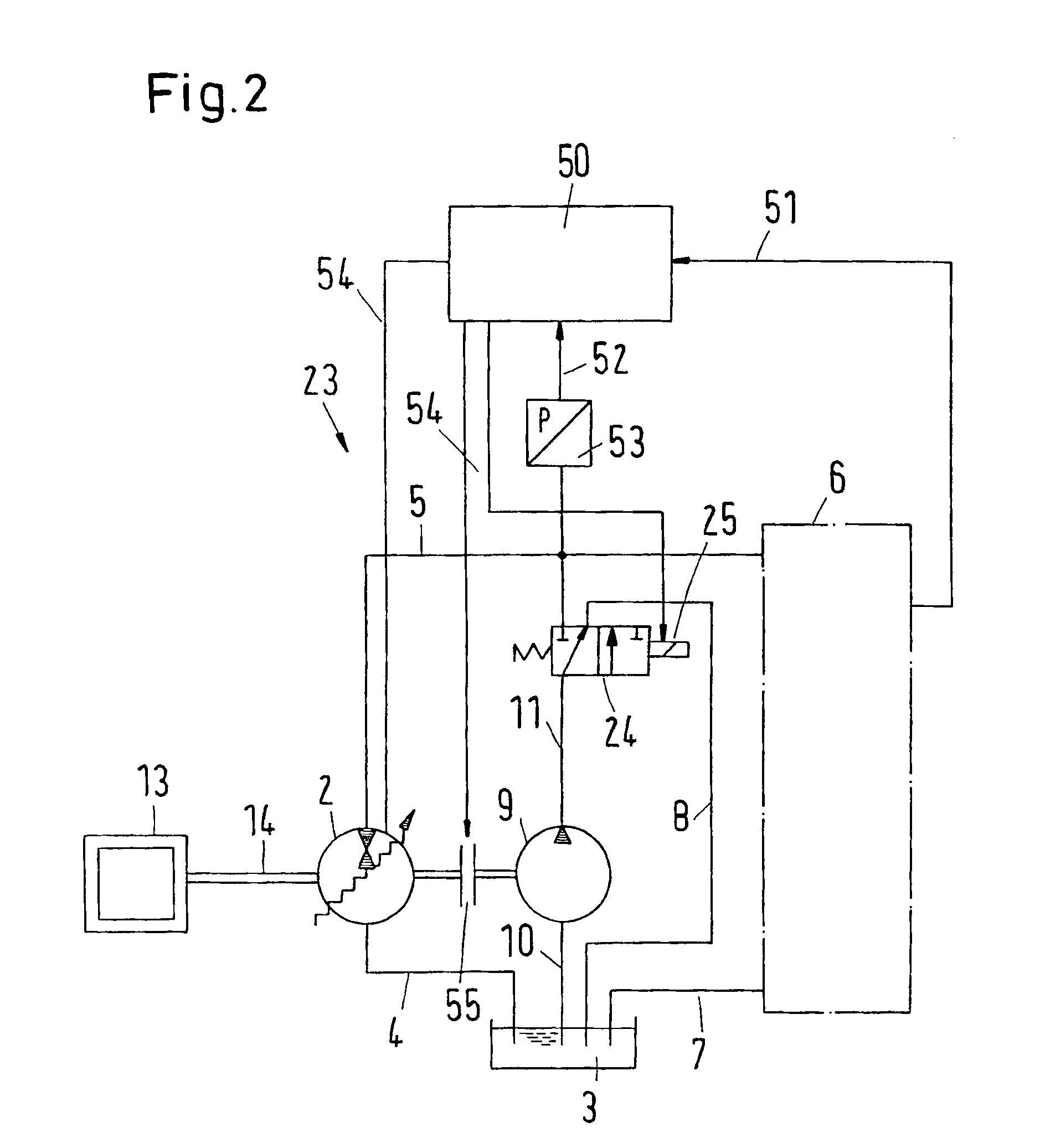
[0012]It is proposed, to design a hydraulic system with at least one hydraulic main pump and at least one hydraulic boost pump for supplying at least one hydraulic consumer, wherein said first hydraulic consumer is connected to the output fluid flow of said hydraulic main pump in a standard operation mode and the output fluid flow of said hydraulic boost pump is selectively added to the output fluid flux of said hydraulic main pump in a boost mode in a way that the combined fluid output flow rate of said hydraulic main pump and said hydraulic boost pump is at least in part regulated by the fluid output flow rate of the main pump. Because the fluid output flow rate of the pump arrangement can be regulated according to the actual demand, it can be avoided, that under low fluid flow demand conditions, a significant amount of high pressure fluid has to be dumped, without performing any useful work. Therefore, the energy efficiency of the proposed hydraulic system can be increased significantly. A key point is that the fluid output flow rate of the main pump is at least in part regulated. Otherwise, dumping of highly pressureised fluid had to be done at a significant flow rate under certain conditions. Such a dumping of high pressure fluid is particularly bad, because the corresponding energy losses are particularly high. Furthermore, the possibility to regulate the fluid output flow rate of the hydraulic main pump is vital in the transition region, when the fluid flow output of the boost pump starts in, or fades out of the combined fluid output flow rate.
[0013]The pumps can be chosen in way, that the maximum output pressure, achievable by said hydraulic main pump is higher than the maximum output pressure, achievable by said hydraulic boost pump. With such an arrangement, the achievable pressure range can be increased. The proposed system is especially well-suited for systems which have requirements for a high pressure during one part of operation and a high flow rate during another part of operation, but it is not possible, due to available power limitation or it is not a duty cycle requirement, to operate both at high pressure and high flow rate at the same time. A main advantage of such a system can be that the boost pump can be selected to have a lower maximum pressure capability than the main hydraulic pump, thus reducing system cost. Particularly, the high level pressure, i.e. the maximum output pressure, achievable by the hydraulic main pump can be in the order of 200 bar, 250 bar or 300 bar, 350 bar, 400 bar, 450 bar or 500 bar. The low pressure level, i.e. the maximum output pressure, achievable by the hydraulic boost pump can be chosen to be in the order of 10 bar, 15 bar, 20 bar, 30 bar, 40 bar, 50 bar, 100 bar, 150 bar, 200 bar, 250 bar or 300 bar.

Problems solved by technology

Such a dumping of high pressure fluid is particularly bad, because the corresponding energy losses are particularly high.
The proposed system is especially well-suited for systems which have requirements for a high pressure during one part of operation and a high flow rate during another part of operation, but it is not possible, due to available power limitation or it is not a duty cycle requirement, to operate both at high pressure and high flow rate at the same time.

Method used


Image

  • Hydraulic system with supplement pump
  • Hydraulic system with supplement pump
  • Hydraulic system with supplement pump

Examples


Embodiment Construction

[0043]FIG. 10 shows a pressure versus flow rate diagram 59, illustrating different working modes I and II. The flow rate is plotted in liters per minute on the abscissa 16. The system pressure is plotted in bars on the ordinate 17, with the maximum required system pressure represented by line 60. In the present example of FIG. 10, the power available from a mechanical power supply, represented by curve 61, exceeds the power which could potentially be drawn from the power supply by the hydraulic system. The maximum power which the hydraulic system could consume is located at the upper right corner of area II, at the intersection of the maximum required system pressure line 60 and the maximum required flow rate line 62. As can be seen from FIG. 10 there is some excess mechanical power supply in the depicted example. This can be seen from the distance between mechanical power limit line 61 and the upper right corner of area II. It is to be understood, that all system pressure / flow rate...


PUM


Abstract

If a hydraulic system has several modes of operation, in particular a mode with a high pressure demand (II) and a mode with a high fluid flow demand (II), the hydraulic fluid pump has to be built with an accordingly high fluid flow output. Such a pump is expensive. Therefore it is suggested, to provide two pumps. I.e. a controllable main pump (2) is provided, which supplies the hydraulic consumer (6) during phases (I) of high pressure demand. During phases (II) of high fluid flow demand, normally, relatively low pressures are sufficient. Therefore, it is suggested to provide a parallel boost pump (9), which supplies the hydraulic consumer (6) in addition to the high pressure pump (2), if a high fluid flow is needed. Excess fluid flow output is avoided by controlling the fluid output flow of main pump 2.

Description

CROSS REFERENCE TO RELATED APPLICATIONS[0001]This application is entitled to the benefit of and incorporates by reference essential subject matter disclosed in International Patent Application No. PCT / DK2008 / 000386 filed on Oct. 29, 2008 and EP Patent Application No. 07254330.9 filed Nov. 1, 2007.FIELD OF THE INVENTION[0002]The invention relates to hydraulic systems with at least one hydraulic main pump and at least one hydraulic boost pump for supplying at least one hydraulic consumer. The invention further relates to a method for operating a hydraulic system. Furthermore the invention relates to a combined pumping system.BACKGROUND OF THE INVENTION[0003]Hydraulic systems are nowadays used in a plethora of technical applications.[0004]In the beginning of hydraulic applications, mostly hydraulic cylinders were used to move heavy weights with high forces. Well known examples are doors for locks, lifting devices for the shovel of a wheel loader, for the fork of a fork-lift truck or fo...

Claims


Application Information

Patent Timeline
Patent Type & Authority Patents(United States)
IPC IPC(8): F04B23/08F04B49/06F04B53/10
CPCF04B23/04F04B23/06F04B1/28F04B49/22F04B49/08F04B1/34
Inventor WADSLEY, LUKECALDWELL, NIALL
Owner DANFOSS PAUER SOLYUSHENS APS
Learn More