Extreme ultraviolet light source apparatus

a light source and ultraviolet technology, applied in the field of extreme ultraviolet (euv) light source devices, can solve the problems of changing and achieve the effect of reducing the changes in the specifications of the euv chamber

Active Publication Date: 2014-03-11
GIGAPHOTON
View PDF46 Cites 2 Cited by
  • Summary
  • Abstract
  • Description
  • Claims
  • Application Information

AI Technical Summary

Benefits of technology

[0009]The present invention has been achieved in view of the above-mentioned problems. A purpose in one aspect of the present invention is to provide an EUV light source apparatus in which changes in specifications of an EUV chamber corresponding to specifications of different processing units can be reduced.
[0011]According to the one aspect of the present invention, since the optical path connection module is provided between the chamber and the processing unit, the specifications of different processing units can be accepted by changing the optical path connection module, and thereby, changes in the specifications of the EUV chamber can be reduced.

Problems solved by technology

Accordingly, there is a problem that it may be necessary to change specifications of an EUV chamber according to the specifications of the processing units.

Method used


Image

  • Extreme ultraviolet light source apparatus
  • Extreme ultraviolet light source apparatus
  • Extreme ultraviolet light source apparatus

Examples


first embodiment

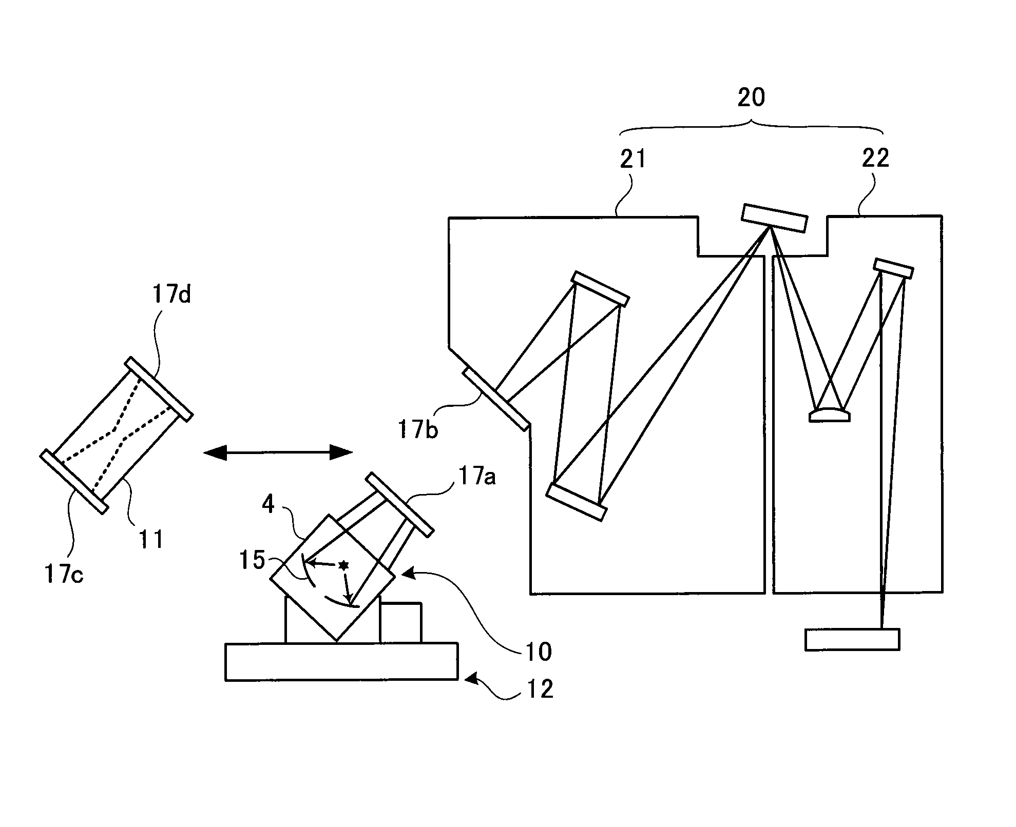
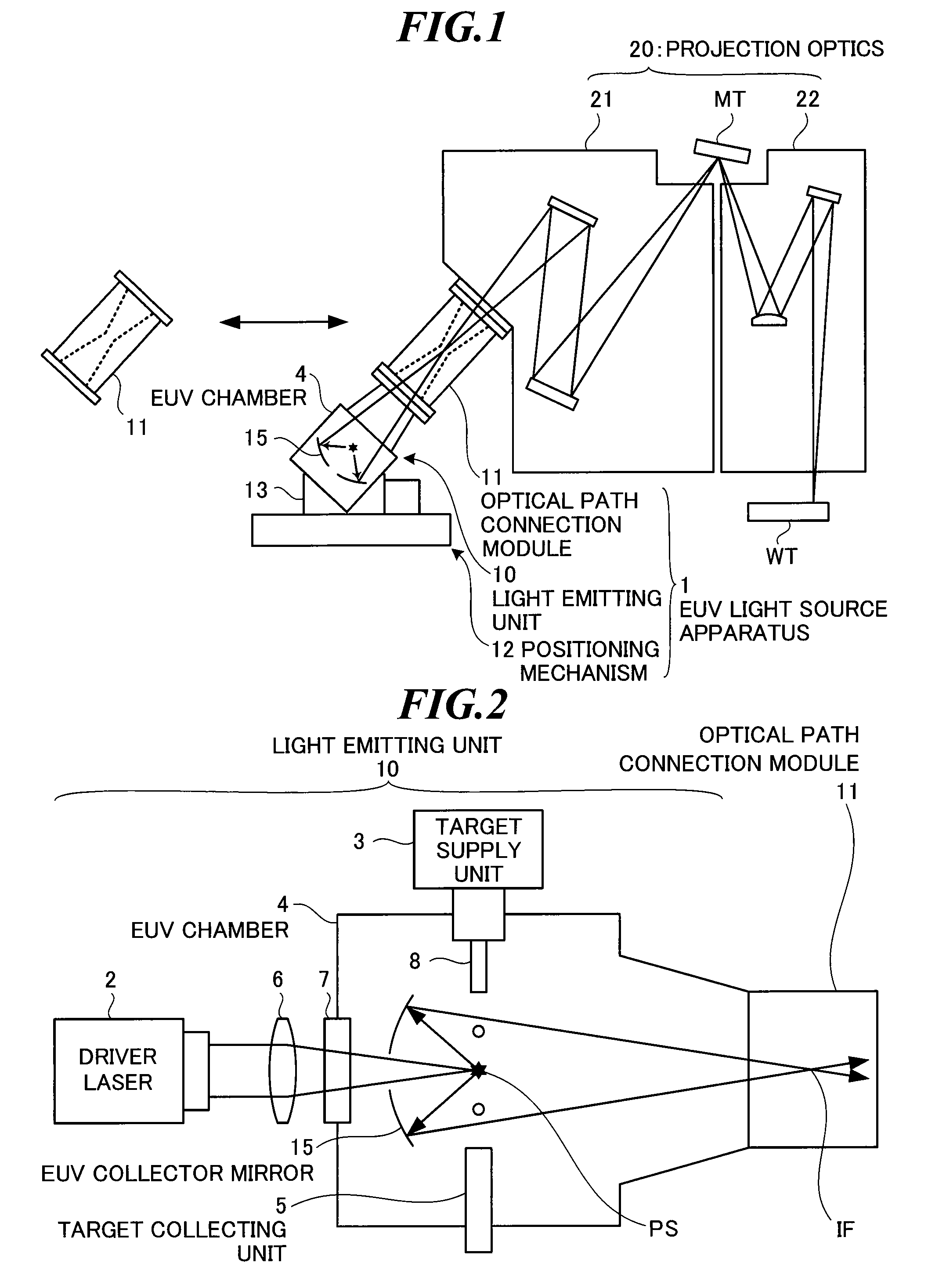
[0028]FIG. 1 is a side view showing a schematic configuration of exposure equipment including an extreme ultraviolet (EUV) light source apparatus according to the present invention. The exposure equipment includes an EUV light source apparatus 1 and projection optics 20. Here, the projection optics 20 is an example of a processing unit for performing processing by using EUV light, and includes a mask irradiation unit 21 as an optics for irradiating a mask with the EUV light, and a workpiece irradiation unit 22 as an optics for projecting a mask pattern on a wafer.

[0029]The EUV light source apparatus 1 according to the first embodiment includes a light emitting unit 10 for generating the EUV light, an optical path connection module 11 provided between the light emitting unit 10 and the projection optics 20, and a positioning mechanism 12 for positioning the light emitting unit 10. The light emitting unit 10 employs an LPP (laser produced plasma) system for generating the EUV light by...

second embodiment

[0105]Next, the second embodiment will be explained.

[0106]FIG. 15 is a schematic diagram showing an outline of a light emitting unit in an EUV light source apparatus according to the second embodiment of the invention. The light emitting unit 10a in the second embodiment employs a DPP (discharge produced plasma) system for emitting EUV light by generating discharge between electrodes and turning a target material into plasma.

[0107]In the DPP system, there are advantages that the EUV light source apparatus can be downsized, and further, the power consumption of the EUV light source apparatus can be reduced.

[0108]The light emitting unit 10a includes a target supply unit 3a, an EUV chamber 4a, a pair of discharge electrodes 9a and 9b, and an EUV collector mirror 15a, and the light emitting unit 10a is connected to the optical path connection module 11.

[0109]The target supply unit 3a is a unit for supplying the target material such as xenon (Xe) gas, lithium (Li) vapor, or tin (Sn) vapo...


PUM


Abstract

An extreme ultraviolet light source apparatus for supplying extreme ultraviolet light to a processing unit for performing processing by using the extreme ultraviolet light. The extreme ultraviolet light source apparatus includes: a chamber in which the extreme ultraviolet light to be supplied to the processing unit is generated; a collector mirror for collecting the extreme ultraviolet light generated in the chamber to output the extreme ultraviolet light to the processing unit; and an optical path connection module for defining a route of the extreme ultraviolet light between the chamber and the processing unit and isolating the route of the extreme ultraviolet light from outside.

Description

CROSS-REFERENCE TO RELATED APPLICATION[0001]The present application claims priority from Japanese Patent Applications No. 2009-105499 filed on Apr. 23, 2009 and No. 2009-268548 filed on Nov. 26, 2009, the contents of which are incorporated herein by reference in their entirety.BACKGROUND OF THE INVENTION[0002]1. Field of the Invention[0003]The present invention relates to an extreme ultraviolet (EUV) light source apparatus to be used in combination with a processing unit for performing processing by using extreme ultraviolet light. For example, the present invention relates to an extreme ultraviolet light source apparatus to be used in combination with projection optics for performing exposure processing of semiconductor wafers in exposure equipment.[0004]2. Description of a Related Art[0005]In recent years, as semiconductor processes become finer, photolithography has been making rapid progress toward finer fabrication. In the next generation, microfabrication at 60 nm to 45 nm, fu...

Claims


Application Information

Patent Timeline
Patent Type & Authority Patents(United States)
IPC IPC(8): G01J3/10
CPCG03F7/70033H05G2/005H05G2/003G03F7/70916G21K1/04H05G2/008
Inventor WATANABE, YUKIOWAKABAYASHI, OSAMUIGARASHI, MIWA
Owner GIGAPHOTON
Why Eureka
Try Eureka