Guidance device

a technology of guidance device and fuze, which is applied in the field of ballistics, can solve the problems of not being able to replace the original fuze with the kit on the battlefield, the effect of increasing the precision of the projectile, and not being able to replace the original fuze with the kit,

Inactive Publication Date: 2014-03-18
BAE SYSTEMS PLC
View PDF26 Cites 18 Cited by
  • Summary
  • Abstract
  • Description
  • Claims
  • Application Information

AI Technical Summary

Benefits of technology

[0009]It is an object of the present invention to provide a collar for guiding a projectile which mitigates at least one of the disadvantages of the prior art identified above.

Problems solved by technology

However, the unit cost of a projectile tends to rise with increased precision.
Further, the act of replacing the original fuze with the kit may be undesirably time consuming, particularly given the urgency with which a muniton may need to be fired.
Indeed, it may not even be possible to replace the original fuse with the kit on the battlefield, for example if some of the payload must be removed as described above.
Further, the kit may only be applicable to munitions which have a detachable fuze.
Where the munition does not originally have a fuze, the kit cannot readily be applied.

Method used


Image

  • Guidance device
  • Guidance device
  • Guidance device

Examples


Embodiment Construction

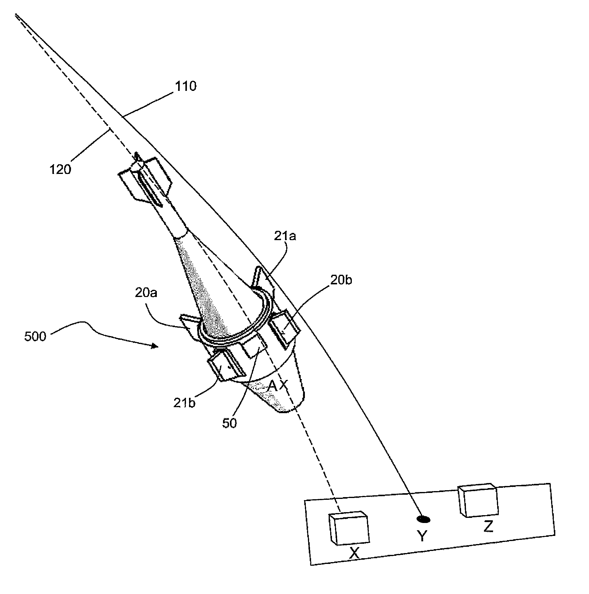
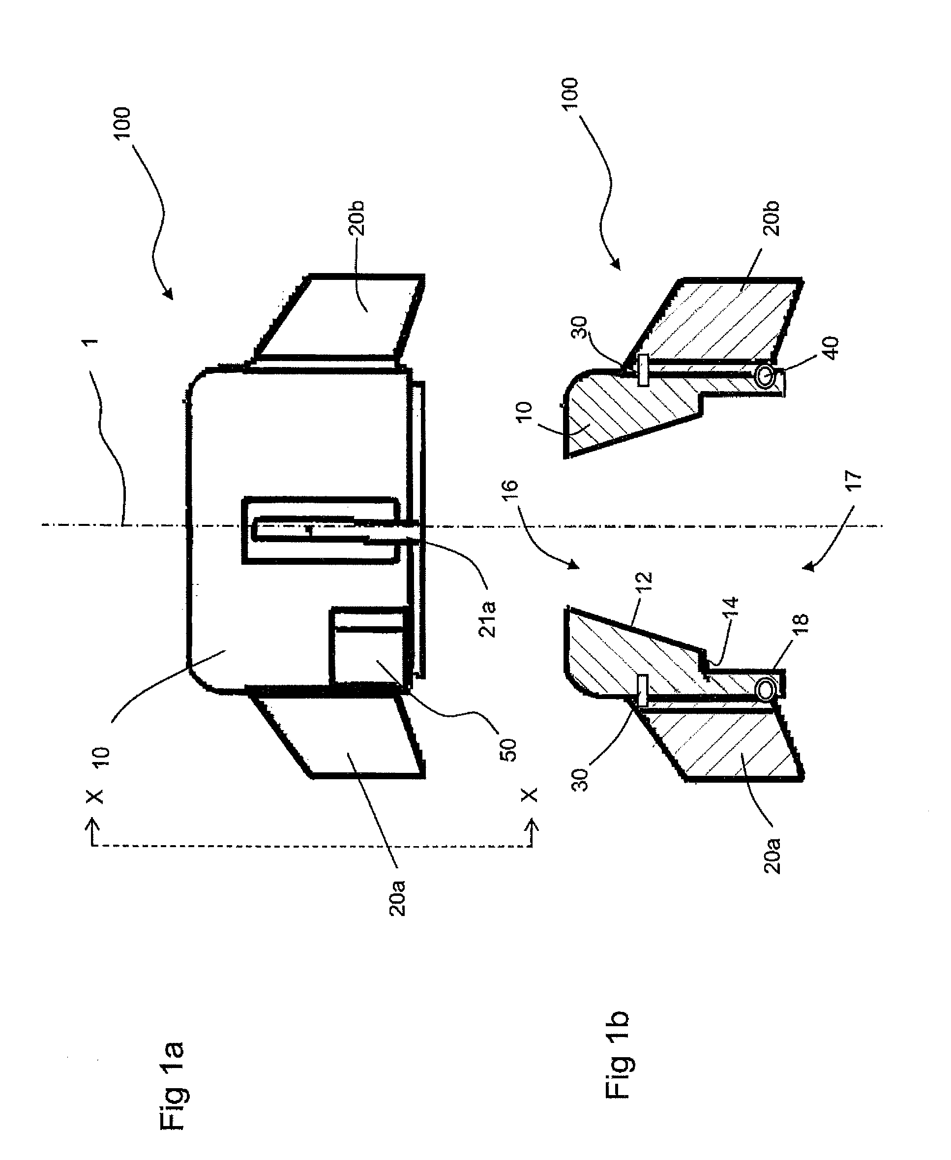
[0046]A collar 100 for guiding a mortar shell, as shown for example in FIG. 1a, FIG. 1b and FIG. 5, comprises a collar body 10. The collar body 10 defines a generally cylindrical outer surface, which defines a collar axis 1. The leading edge of the collar (that is the top edge in FIG. 1a) is filleted so as to have appropriate aerodynamic properties.

[0047]A plurality of canards 20a, 20b, 21a and 21b extend from the outer surface of the collar body 10. The plurality of canards 20a, 20b, 21a and 21b are spaced at regular intervals about the outer surface of the collar body 10. The canards are arranged in pairs. A first canard pair, consisting of canard 20a and 20b, generally occupies a first plane with canards 20a and 20b mounted on diametrically opposite sides of the collar body 10. A second canard pair, consisting of canard 21a and 21b, generally occupies a second plane with canards 21a and 21b mounted on diametrically opposite sides of the collar body 10

[0048]Each canard is pivotall...


PUM


Abstract

There is disclosed a collar (100) which may be attached to a munition in order to control the trajectory of the munition. The collar (100) has a collar body (10); a surface (12) for capturing the projectile as it leaves the barrel; a sill (14) for supporting the surface (12) at the muzzle of the barrel; and a guidance means (20a, 20b, 21a, 21b) for altering the flow of air around the collar (100). The collar (100) supports itself at the muzzle and may attach to the projectile at the surface (12) to integrate with the projectile as the projectile is fired. The collar (100) is particularly suited for attachment to mortar rounds. Such a collar (100) gives a weapon operator the option of increasing the precision of a munition without having to carry a plurality of munition types.

Description

[0001]The present invention relates to a guidance device comprising a collar for guiding a projectile, and in particular to a collar for improving the precision of a ballistic projectile.BACKGROUND OF THE INVENTION[0002]In the field of ballistics, the term precision describes the ability of a projectile, fired from a weapon system, to follow a predicted trajectory and hence hit an expected target; a precise projectile will, by definition, follow a predicted trajectory more closely than an imprecise projectile. Ballistic precision is commonly measured using the circular error probability (CEP).[0003]In most cases, it is desirable to have a precise projectile. However, the unit cost of a projectile tends to rise with increased precision. Accordingly, it is generally understood that in designing projectiles, the benefit of providing a particularly precise projectile must be balanced against the costs of such provision.[0004]It is known to have a kit, such as the XM1156 Precision Guidan...

Claims


Application Information

Patent Timeline
Patent Type & Authority Patents(United States)
IPC IPC(8): F42B10/62F42B10/14F42B10/00
CPCF42B10/46F42B10/12F42B10/14F42B10/64
Inventor AXFORD, RICHARD DESMOND JOSEPHBEGGS, KEVIN WILLIAM
Owner BAE SYSTEMS PLC
Why Eureka
Try Eureka