Routing bandwidth guaranteed paths with local restoration in label switched networks

a technology of label switching and routing paths, applied in the field of label switching networks, can solve the problems of large restoration latencies of the order of seconds or at best 100 s of milliseconds, variable second and third components of end-to-end restoration, and delay equal to the amount of time elapsed before corrective action, so as to minimize bandwidth usage and free excess bandwidth

Active Publication Date: 2014-03-18
WSOU INVESTMENTS LLC
View PDF41 Cites 170 Cited by
  • Summary
  • Abstract
  • Description
  • Claims
  • Application Information

AI Technical Summary

Benefits of technology

[0009]A backtracking distance over the primary routing path is determined, and costs for at least one restoration path are assigned. The at least one restoration path may then be computed base...

Problems solved by technology

This causes very large restoration latencies of the order of seconds or at best 100 s of milliseconds.
Accordingly, the second and third components of end-to-end restoration are variable and difficult to bound.
In particular, in a true local restoration scenario, the delay before corrective action is taken equals the amount of time elapsed before a link owner node detects the link failure.
However, a link owner may not have capabilities of providing restoration during a link failure.
That is,...

Method used


Image

  • Routing bandwidth guaranteed paths with local restoration in label switched networks
  • Routing bandwidth guaranteed paths with local restoration in label switched networks
  • Routing bandwidth guaranteed paths with local restoration in label switched networks

Examples


first embodiment

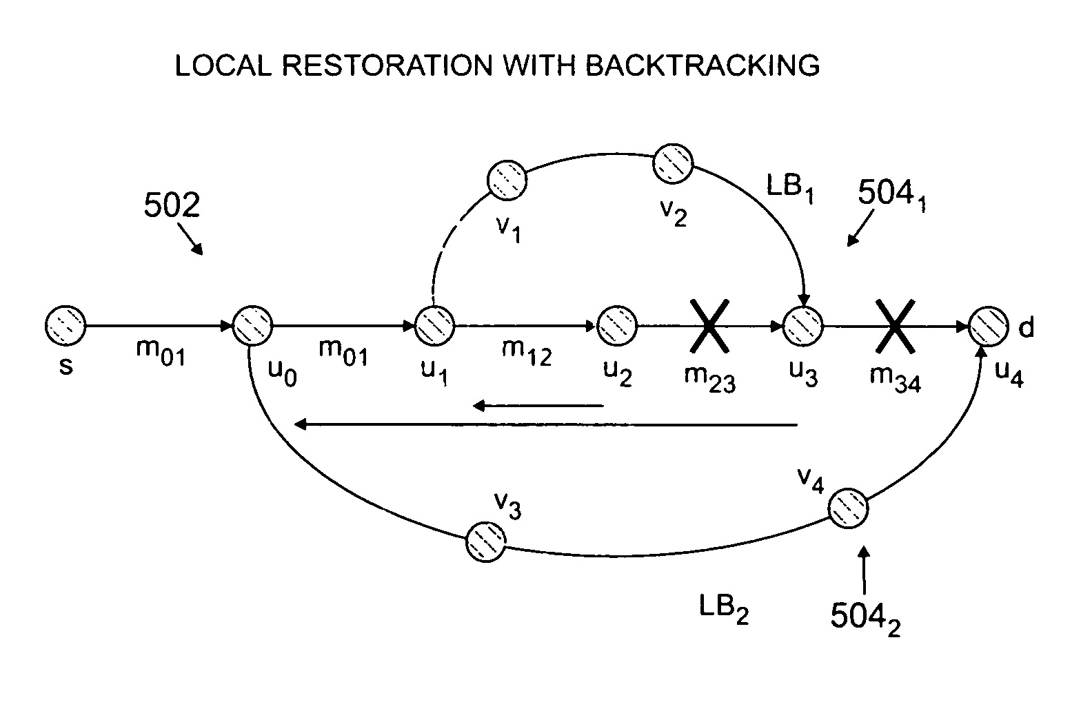
[0073]Referring to FIG. 1, at step 110, a determination is made regarding the backtracking distance to be used to compute the restoration paths. The present invention includes three backtracking distance embodiments. A first embodiment includes no backtracking (D=0). In this case, the backup path must originate at the node at which the failed link originates, which represents true local restoration and provides best restoration latency. The link restoration paths computed for D=0 can use a subset of primary path links downstream towards the destination node.

second embodiment

[0074]A second embodiment includes bounded backtracking (D=k), where k equals some integer greater than zero (0). In this embodiment, the backup path can originate at a node on the primary path up to “k” hops away from the node that owns the link.

third embodiment

[0075]A third embodiment includes infinite backtracking (D=∞). In this instance, unlimited backtracking is permissible, and therefore in the worst case, the backtracking may result in backup paths that originate at the source node. The end-to-end restoration may be considered a special case of this where the maximum backtracking allowed is equal to length of the primary path, however the restoration always has to be initiated at the source node.

[0076]The first backtracking embodiment (i.e., D=0) may require the highest amount backup bandwidth and lowest restoration latency, whereas the third backtracking embodiment (i.e., D=∞) requires the least amount of bandwidth and highest restoration latency. The second backtracking embodiment (i.e., D=k, where k is an integer greater than 0) provides a tradeoff of bandwidth utilization for better restoration latency.

[0077]It is noted that the sharing of links on backup paths exploits the fault model and the restoration mechanisms as described ...


PUM


Abstract

A method of providing at least one restoration path for a primary routing path in a network. The method includes receiving a customer connection request to route information. Costs are assigned for the primary routing path, and the primary routing path is computed based upon the primary routing path costs. A backtracking distance over the primary routing path is determined, and costs for at least one restoration path are assigned. The at least one restoration path may then be computed based upon the at least one restoration path costs.

Description

FIELD OF INVENTION[0001]The present invention relates to label switched networks. More specifically, the present invention relates to restoration of routing paths.DESCRIPTION OF THE BACKGROUND ART[0002]The emerging label switched networks, such as multi-protocol label switching (MPLS) networks and wavelength division multiplexing (WDM) networks, enable network service providers to route bandwidth guaranteed paths between customer sites. The basic label switched path (LPS) routing is often enhanced using restoration routing, which sets up alternate LSPs to guarantee uninterrupted network connectivity in case network links or nodes fail.[0003]There are two variants of restoration routing. A first restoration technique is known as global (i.e., “end-to-end”) restoration, which provides two disjoint paths between an ingress (source) node and an egress (destination) node. Resources are always reserved on the restoration path and are guaranteed to be available when the restoration path is...

Claims


Application Information

Patent Timeline
IPC IPC(8): H04L12/28H04L12/56G06F11/07
CPCH04L45/22H04L45/28H04L45/12
Inventor BUDDHIKOT, MILIND M.CHEKURI, CHANDRA S.GUO, KATHERINE H.LI, LI
Owner WSOU INVESTMENTS LLC
Why Eureka
Try Eureka