Centrifuge with a coupling element for axially locking a rotor

a technology of axial locking and centrifuge, which is applied in the direction of centrifuges, etc., can solve the problems of the rotor not being able to unlock the coupling element, and achieve the effect of preventing wear and tear, being easy to mount on the rotor, and performing very easily

Active Publication Date: 2014-03-25
THERMO ELECTRONICS LED GMBH
View PDF14 Cites 21 Cited by
  • Summary
  • Abstract
  • Description
  • Claims
  • Application Information

AI Technical Summary

Benefits of technology

[0007]The coupling element is able to cause a self-locking by means of a ramp surface inclined in such a way, so that the rotor is unable to unlock the coupling element during standstill, low or high rotational speed. Such an effect is especially advantageous during standstill because the user can make sure by an attempted withdrawal of the rotor from the drive head whether the rotor is also securely locked. During high rotational speed, the locking force increases as a result of the ramp surface because the axial force component also increases with increasing centrifugal force.
[0016]In a further embodiment of the present invention, the cylindrical surface of the drive head is arranged as a clearance fit in relation to the holding surface of the rotor or the sleeve, which clearance fit ensures secure guidance of the rotor during standstill and at a high rotary speed. A clearance fit can be produced relatively simply and at low cost.

Problems solved by technology

The coupling element is able to cause a self-locking by means of a ramp surface inclined in such a way, so that the rotor is unable to unlock the coupling element during standstill, low or high rotational speed.

Method used


Image

  • Centrifuge with a coupling element for axially locking a rotor
  • Centrifuge with a coupling element for axially locking a rotor
  • Centrifuge with a coupling element for axially locking a rotor

Examples


Embodiment Construction

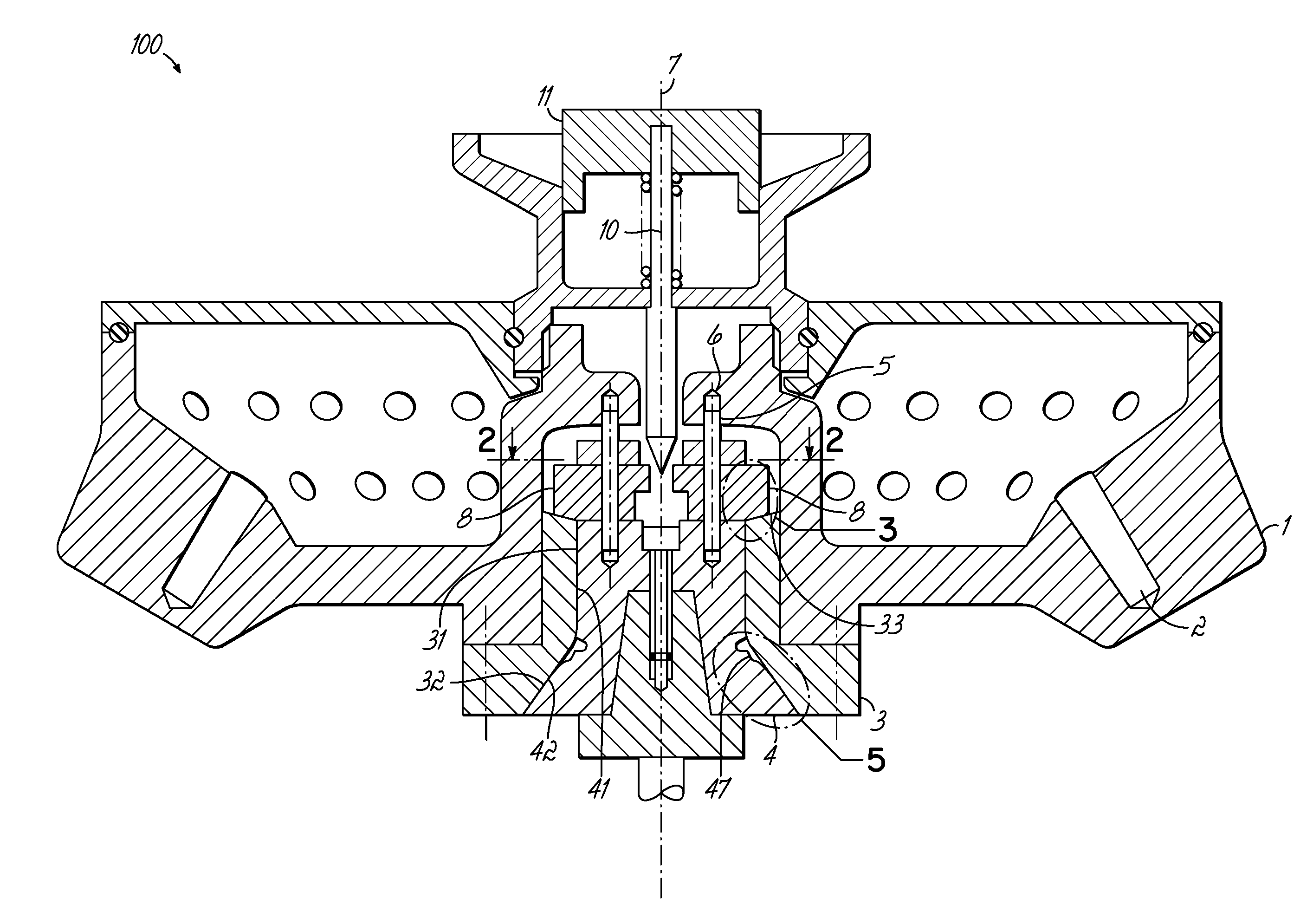
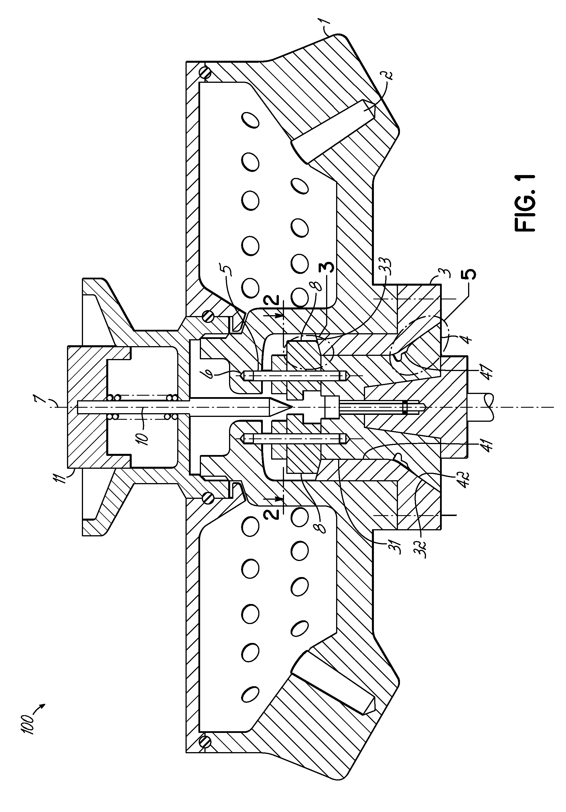
[0024]FIG. 1 shows a cross-sectional view of a centrifuge 100 in accordance with the invention without any substructure. Centrifuge 100 comprises a rotor 1 which comprises a plurality of recesses 2 for accommodating sample containers with substances to be centrifuged. A sleeve 3 is mounted on the rotor 1, which sleeve rests in an interlocking manner on a drive head 4. Two vertically extending connection elements 5 in the form of pins are attached to the drive head 4, which pins each engage in an interlocking manner in a recess 6 in rotor 1. In the embodiment as shown in FIG. 1 there are two connection elements 5 which are arranged symmetrically in relation to the rotary axis 7. It is also possible to provide more than two connection elements 5. During a rotary movement of the drive head 4 about the rotary axis 7, these connection elements 5 transmit a torque onto rotor 1, so that it can be made to rotate. It is achieved by the symmetric arrangement of the connection elements 5 that ...


PUM


Abstract

The invention relates to a centrifuge with a drive head which can be connected with a drive, a rotor which can detachably be mounted on the drive head, at least one connection element with which the drive head can be connected in a torsion-proof manner with the rotor, and at least one coupling element which is attached to the drive head and is able to exert an axial force on the rotor in such a way that the rotor can be fixed axially, with the axial force increasing with the rising rotational speed of the drive head, with the coupling element on the rotor transmitting the axial force by means of a ramp surface which is inclined at an angle (α) relative to the horizontal line in a range of more than 0° to 15°. Secure locking of the rotor during standstill and high speeds can thus be achieved.

Description

FIELD OF THE INVENTION[0001]The present invention relates to a centrifuge with a drive head which can be connected with a drive, a rotor which can detachably be mounted on the drive head, at least one connection element with which the drive head can be connected in a torsion-proof manner with the rotor, and at least one coupling element which is attached to the drive head and is able to exert an axial force on the rotor in such a way that the rotor can be fixed axially, with the axial force increasing with the rising rotational speed of the drive head.BACKGROUND OF THE INVENTION[0002]A centrifuge can receive containers for samples and can be used for separating components of the samples contained therein at high rotational speed of a centrifuge rotor. In the case of a floor-stand centrifuge which is arranged on the floor and has a height which reaches up to a worktable, there is a fair amount of space for the components of the device. In the case of a desktop centrifuge however whic...

Claims


Application Information

Patent Timeline
Patent Type & Authority Patents(United States)
IPC IPC(8): B04B7/06
CPCB04B2009/085B04B9/08B04B2007/025
Inventor HENNE, SEBASTIAN
Owner THERMO ELECTRONICS LED GMBH
Why Eureka
Try Eureka