Spring operated switch actuator with damper for an electrical switching apparatus

a technology of electrical switching apparatus and actuator, which is applied in the direction of snap-action arrangements, contact mechanisms, motors, etc., can solve the problem of space-consuming dampers, and achieve the effect of reliable and precis

Active Publication Date: 2014-03-25
HITACHI ENERGY LTD
View PDF11 Cites 2 Cited by
  • Summary
  • Abstract
  • Description
  • Claims
  • Application Information

AI Technical Summary

Benefits of technology

[0011]The object of the present invention is to overcome drawbacks related to conventional spring operated actuators with regard to the damping of such. In particular the object is to provide a damper for the closing that requires small space and few components and which is reliable and precise.

Problems solved by technology

Such a damper is space-consuming and requires a plurality of components to be connected to the drive mechanism of the actuator.

Method used


Image

  • Spring operated switch actuator with damper for an electrical switching apparatus
  • Spring operated switch actuator with damper for an electrical switching apparatus
  • Spring operated switch actuator with damper for an electrical switching apparatus

Examples


Embodiment Construction

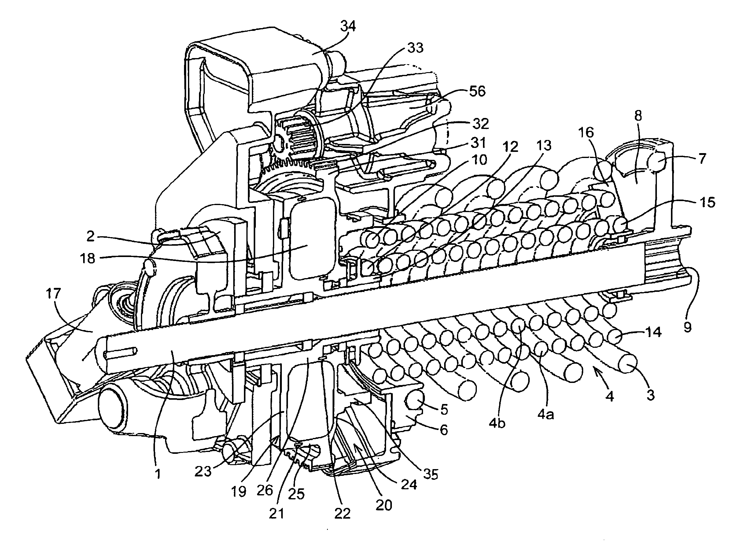
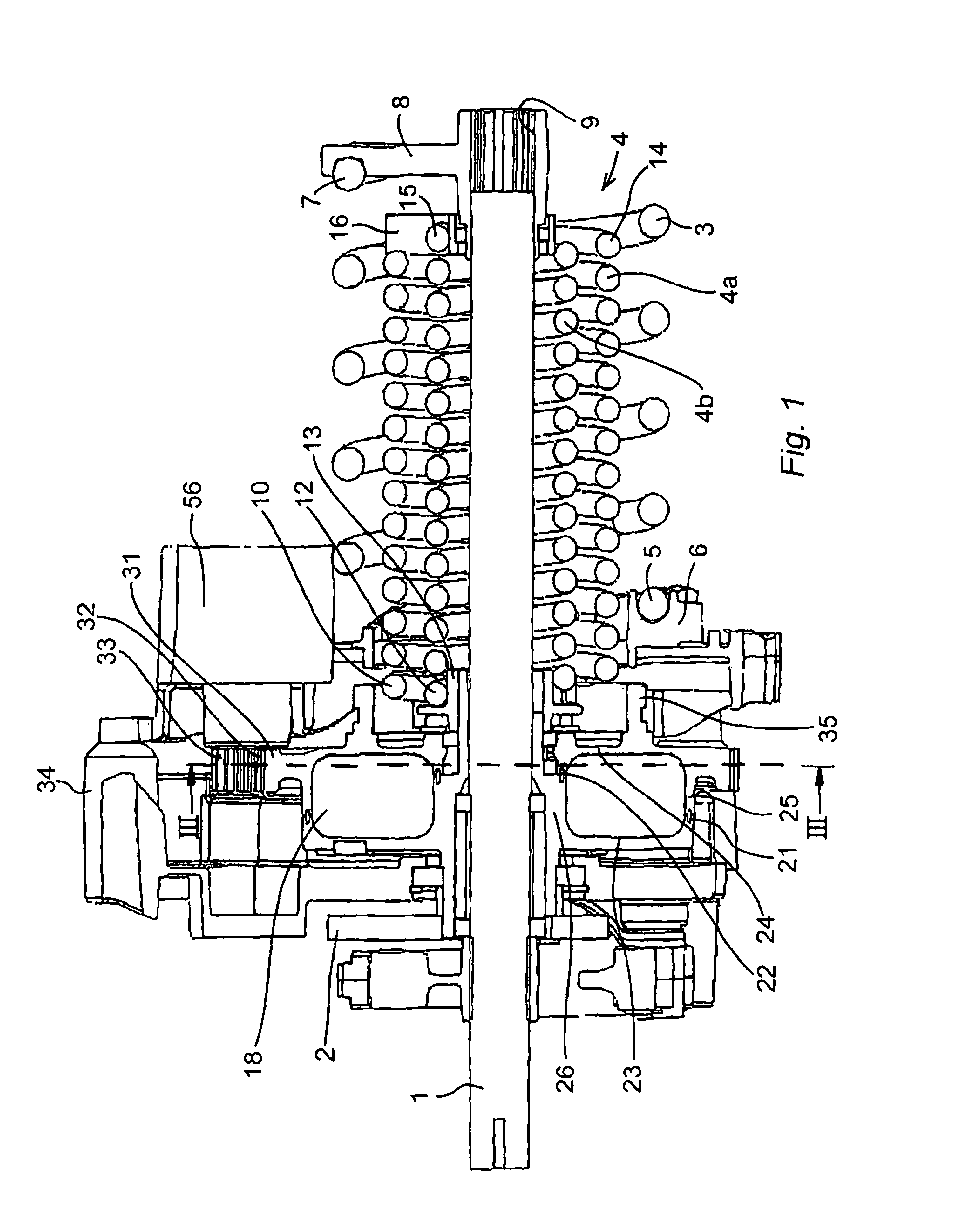
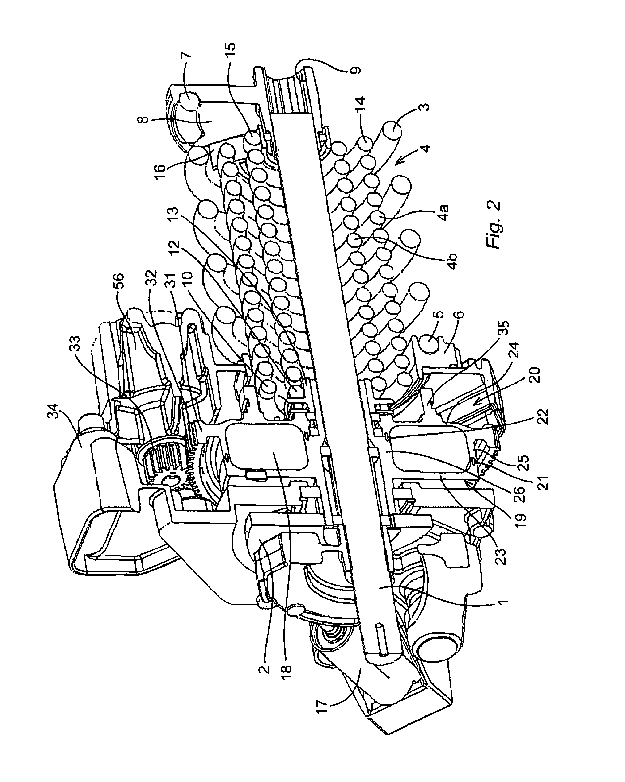
[0063]FIG. 1 is an axial section through the actuator of a circuit breaker. The actuator has a main shaft 1 and a cam disc 2. The cam disc acts on the transmission rod (not shown) for switching the circuit breaker. The transmission from the cam disc to the circuit breaker and the circuit breaker as such can be of a conventional kind and need no further explanation.

[0064]The main shaft is operated by an opening spring 3 and a closing spring 4. Both the springs are helical torsion springs and are coaxial with the main shaft. The opening spring 3 is located radially outside the closing spring 4 and thus has an internal diameter exceeding the external diameter of the closing spring 4.

[0065]The opening spring 3 is squeezed between two end fittings, a supporting end fitting 6 at the supported end 5 of the spring and an actuating end fitting 8 at its actuating end 7. The opening spring 3 thus in its charged state is compressed in the direction of its helix, or otherwise expressed the charg...


PUM


Abstract

A spring operated actuator for an electrical switching apparatus. It includes an opening spring, a closing spring and a damper for the closing. The damper is a rotary air damper with components that rotate relative to each other and has air as working medium for the dampening.

Description

CROSS-REFERENCE TO RELATED APPLICATIONS[0001]The present application is a continuation of pending International patent application PCT / EP2010 / 066391 filed on Oct. 28, 2010 which designates the United States and claims priority from European patent application 09174926.7 filed on Nov. 3, 2009. The content of all prior applications is incorporated herein by reference.FIELD OF THE INVENTION[0002]The present invention relates to a spring operated actuator for an electrical switching apparatus, the spring operated actuator including an opening spring and a closing spring to provide an opening and a closing movement respectively of the switching apparatus and including a damper connected to the closing spring and arranged to decelerate the closing movement during at least an end portion of the movement.BACKGROUND OF THE INVENTION[0003]In a power transmission or distribution network, switching apparatuses are incorporated into the network to provide automatic protection in response to abno...

Claims


Application Information

Patent Timeline
Patent Type & Authority Patents(United States)
IPC IPC(8): H01H5/00
CPCH01H3/3026H01H3/605H01H3/3015H01H3/3042
Inventor STAFFAS, DANIELHOLMAN, MATS
Owner HITACHI ENERGY LTD
Why Eureka
Try Eureka