Multi-position solar panel rack

a solar panel and rack technology, applied in the field of racks, can solve the problems of increasing the cost of building and maintaining the system, increasing the cost of installing a tracking system to keep the collector more perpendicular to the sun, and increasing the cost of maintaining the system. , to achieve the effect of maximizing strength and minimizing materials

Active Publication Date: 2014-04-01
ABAR WARREN
View PDF49 Cites 32 Cited by
  • Summary
  • Abstract
  • Description
  • Claims
  • Application Information

AI Technical Summary

Benefits of technology

[0010]The present racking system uses space frame technology to minimize materials while maximizing strength. The rack has multi-position racking capability, using a simple swing arm and pin system to move the solar array into an optimum position for the appropriate time of the year.
[0015]In a preferred embodiment, locking means secures the array support in each of the multiple positions.

Problems solved by technology

Maintaining a collector perpendicular to the sun as it arcs across the sky at a slightly different elevation every day is expensive because of the need for a system to track the sun.
The cost to implement a tracking system to keep the collector more perpendicular to the sun can be expensive when compared to the amount of additional energy harvested.
The cost to build and maintain the system when compared to the value of the additional useful energy derived from the system determines the return on investment.
One of the main limitations of most swivel based systems is that they are a challenge to operate quickly given the weight of the system.
Manually adjusted systems with a single pivot point have a single point of failure.

Method used


Image

  • Multi-position solar panel rack
  • Multi-position solar panel rack
  • Multi-position solar panel rack

Examples


Embodiment Construction

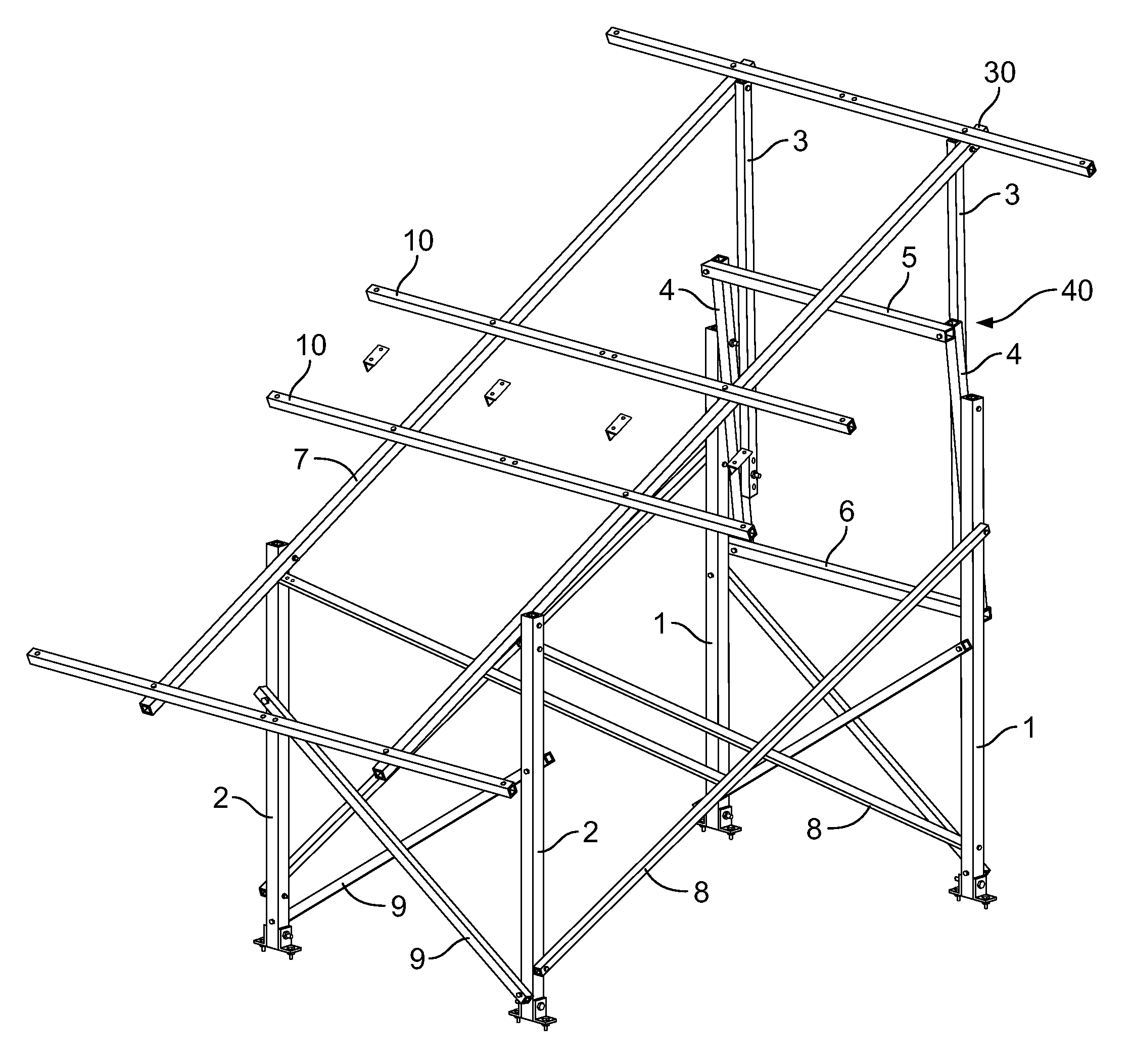
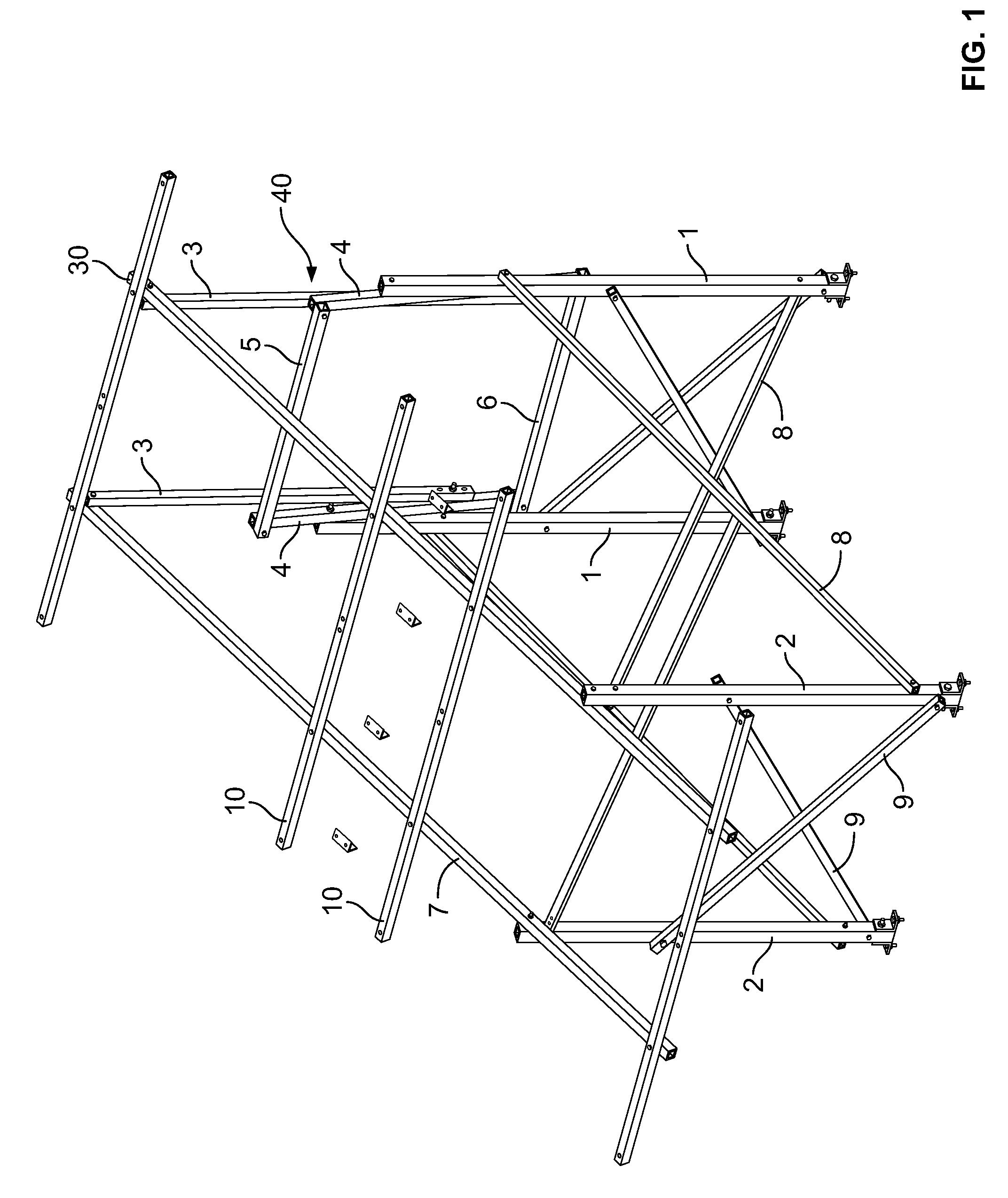
[0027]The present racking system uses space frame technology to minimize materials while maximizing strength. The rack has multi-position racking capability, using a simple swing arm and pin system to move the solar array into an optimum position for the appropriate time of the year.

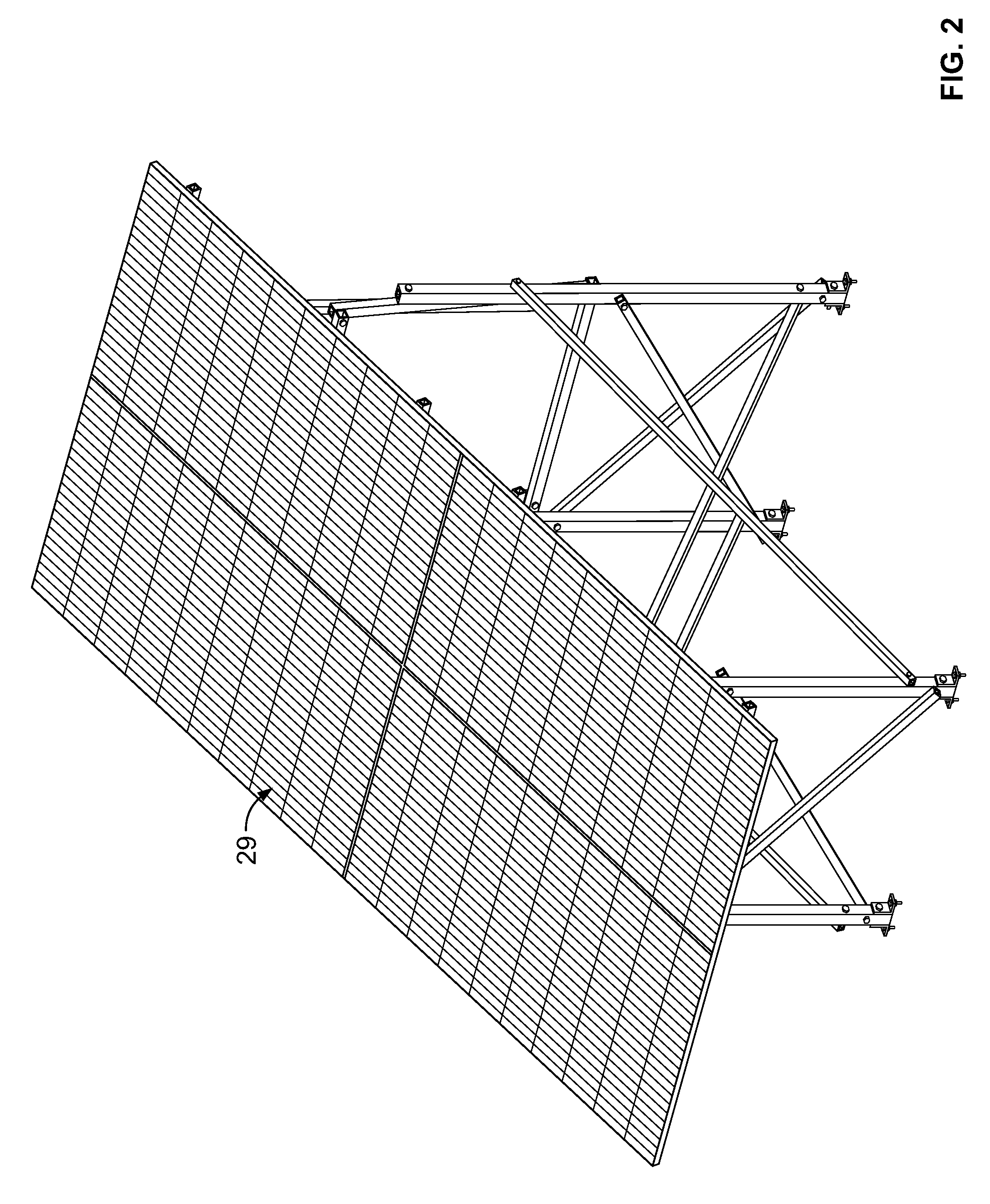
[0028]In accordance with the invention, as best seen in the Figures, the preferred embodiment of the invention includes two back legs 1, two front legs 2, with cross braces 8,9 to support the legs 1, 2. Connected to the upper end of each front leg 2 is back bone 7, and secured along the length of the back bone 7 is a plurality of ribs 10. In this embodiment, the back bone 7 comprises two aluminum bars, while there are four aluminum ribs which are aligned perpendicular to the back bone 7. The back bone 7 and the plurality of ribs make up an array support 30, upon which a typical solar panel array 29 is mounted.

[0029]Located between the upper end of the back legs 1 and the back bone 7 is swing arm mechanis...


PUM


Abstract

The present racking system uses space frame technology to minimize materials while maximizing strength. The rack has multi-position racking capability, using a simple swing arm and pin system to move the solar array into an optimum position for the appropriate time of the year.

Description

FIELD OF THE INVENTION[0001]This invention relates to a rack for mounting an array of solar panels. Specifically, a multi-position rack using a swing arm and pins.BACKGROUND OF THE INVENTION[0002]Solar energy is the collection of the sun's energy by systems which convert the power to electricity and / or thermal power. The efficiency of the system determines how much of the sun's energy is collected and utilized.[0003]The positioning of the collector relative to the sun is an important area of research to optimize the power harvested by the system. The more perpendicular the collector is to the sun, the more energy is collected.[0004]When the collector is perpendicular to the sun, the inbound radiant energy density per unit area is maximized. Maintaining a collector perpendicular to the sun as it arcs across the sky at a slightly different elevation every day is expensive because of the need for a system to track the sun. This typically includes sensors, motors and pivots.[0005]The co...

Claims


Application Information

Patent Timeline
Patent Type & Authority Patents(United States)
IPC IPC(8): F24J2/00
CPCY02E10/50F24J2/541F24J2/5264F24J2/5233F24J2002/5455Y02E10/47H01L31/0422H02S20/00H02S20/30H02S20/23H02S20/10F24S2030/132F24S25/13F24S30/425F24S25/70Y02B10/10
Inventor ABAR, WARREN
Owner ABAR WARREN
Why Eureka
Try Eureka