Solenoid valve for liquid propane injection system

a solenoid valve and liquid propane technology, which is applied in the direction of magnets, machines/engines, magnets, etc., can solve the problems of loss of function, difficulty in maintaining and repairing the fuel pump, and inability to supply fuel smoothly, so as to maintain the fuel-sending performance of the fuel pump

Inactive Publication Date: 2014-04-01
HYUNDAI MOTOR CO LTD +1
View PDF16 Cites 8 Cited by
  • Summary
  • Abstract
  • Description
  • Claims
  • Application Information

AI Technical Summary

Benefits of technology

[0018]Various aspects of the present invention provide for a solenoid valve for an LPI (Liquid Propane Injection) system that can prevent bubbles from flowing into a fuel pump due to heat from a solenoid coil, when a vehicle that travels at low speed is instantaneously and rapidly accelerated, and keep the vehicle stably traveling by maintaining the fuel-sending performance of the fuel pump.
[0019]Various aspects of the present invention provide for a solenoid valve for a liquid propane injection system, which includes a sealing member that is fitted on the outer circumferential surface of a pressure valve which is connected with a bomb-coupling portion to prevent connection between the gap, which is in between the bomb-coupling portion and the pressure valve, and the outside; and a sealing-reinforcing member that is integrally formed in contact with the sealing member at the end of the bomb-coupling portion which faces the sealing member in order to reinforce airtightness between the bomb-coupling portion and the sealing member.
[0023]According to various aspects of the present invention, it is possible to prevent bubbles from flowing into a fuel pump due to heat from a solenoid coil, when a vehicle that travels at low speed is instantaneously and rapidly accelerated, using the sealing member and the sealing-reinforcing member, and accordingly it is possible to keep the vehicle stably traveling by maintaining the fuel-sending performance of the fuel pump and smoothly supplying fuel to injectors.

Problems solved by technology

The fuel pump of the LPI system is usually disposed in the bomb and in this case it is not easy to maintain and repair the fuel pump, such that fuel pump 2 may be disposed outside bomb 1, as shown in FIG. 1.
As bubbles 25 flow into fuel pump 2, as described above, fuel pump 2 loses the function of instantaneously sending the fuel and fuel is not smoothly supplied to injectors 3, such that the traveling of the vehicle becomes unstable.

Method used


Image

  • Solenoid valve for liquid propane injection system
  • Solenoid valve for liquid propane injection system
  • Solenoid valve for liquid propane injection system

Examples


Embodiment Construction

[0033]Reference will now be made in detail to various embodiments of the present invention(s), examples of which are illustrated in the accompanying drawings and described below. While the invention(s) will be described in conjunction with exemplary embodiments, it will be understood that present description is not intended to limit the invention(s) to those exemplary embodiments. On the contrary, the invention(s) is / are intended to cover not only the exemplary embodiments, but also various alternatives, modifications, equivalents and other embodiments, which may be included within the spirit and scope of the invention as defined by the appended claims.

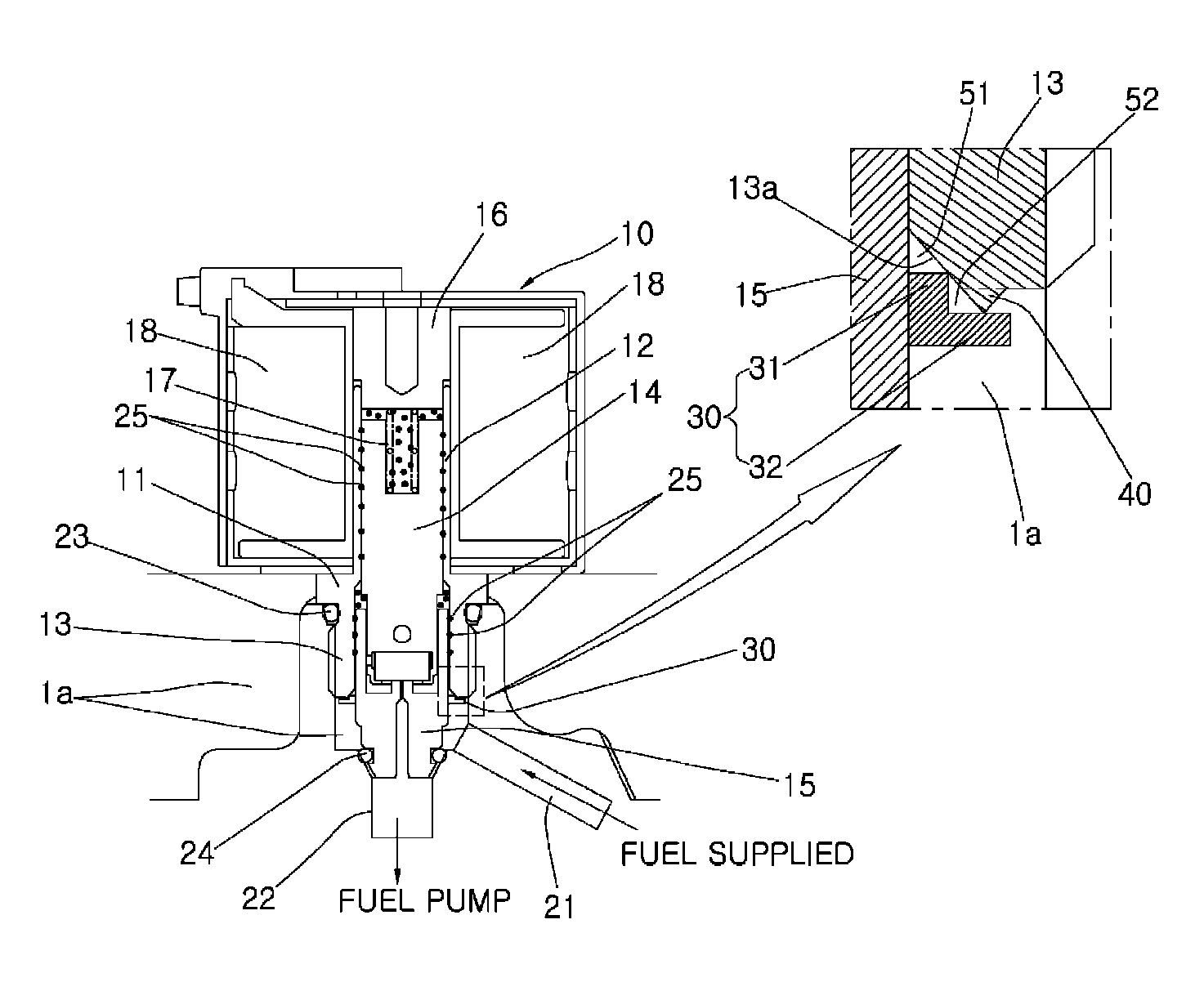
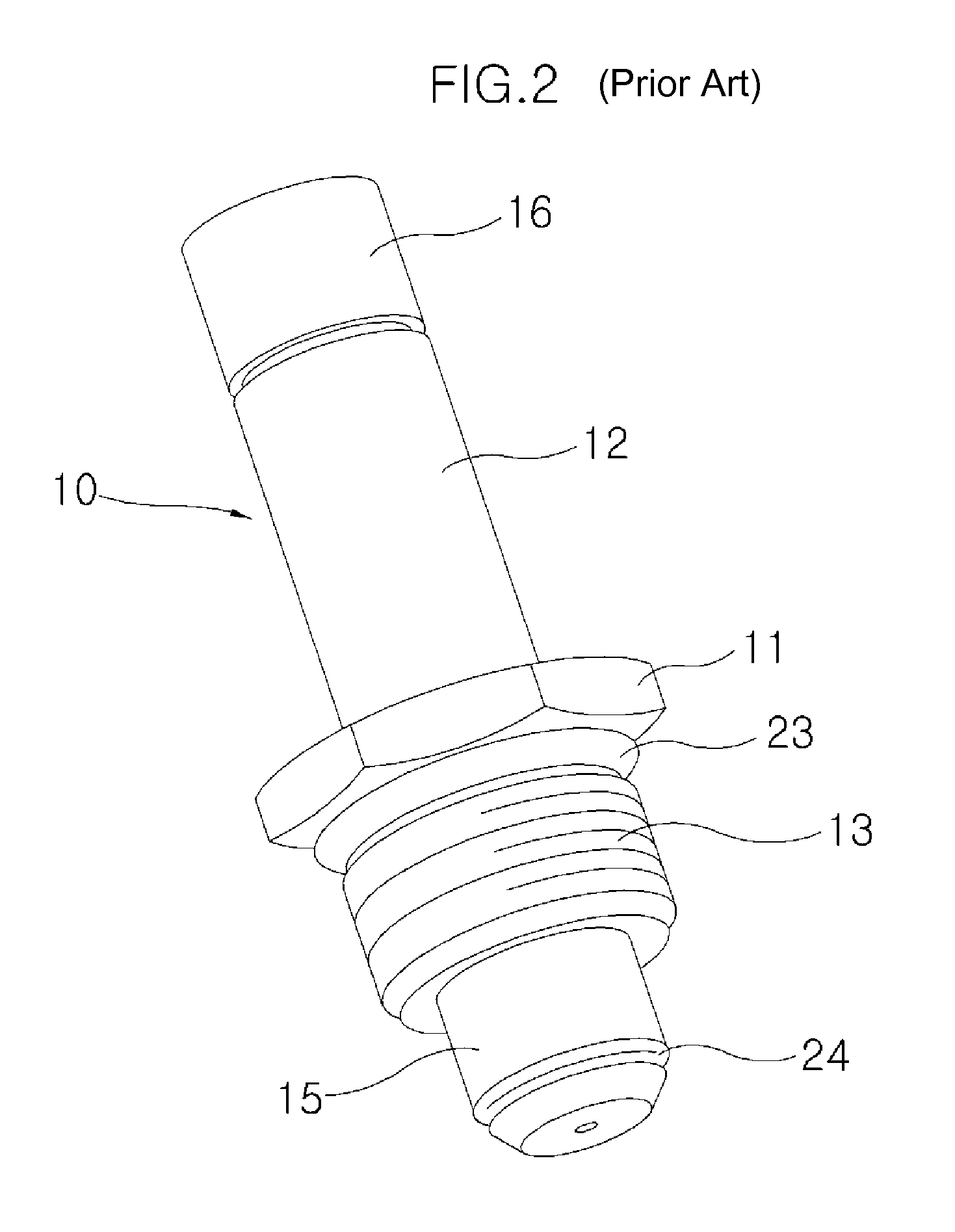
[0034]A solenoid valve 10 for an LPI (Liquid Propane Injection) system, as shown in FIGS. 5 and 6, has a plunger housing 12 at one side from a tool-coupling portion 11 and a bomb-coupling portion 13 at the other side. A plunger 14 is inserted in plunger housing 12 and a pressure valve 15 is disposed in bomb-coupling portion 13, in whi...


PUM

PropertyMeasurementUnit
speedaaaaaaaaaa
pressureaaaaaaaaaa
poweraaaaaaaaaa

Abstract

A solenoid valve for a liquid propane injection system can prevent bubbles from flowing into a fuel pump due to heat from a solenoid coil, when a vehicle that travels at low speed is instantaneously and rapidly accelerated, using a sealing member and a sealing-reinforcing member, and accordingly keep the vehicle stably traveling by maintaining the fuel-sending performance of the fuel pump and smoothly supplying fuel to injectors.

Description

CROSS-REFERENCE TO RELATED APPLICATIONS[0001]The present application claims priority to Korean Patent Application Number 10-2010-0123860 filed Dec. 6, 2010, the entire contents of which application is incorporated herein for all purposes by this reference.BACKGROUND OF INVENTION[0002]1. Field of Invention[0003]The present invention relates to a solenoid valve for a liquid propane injection system, and more particularly, to a solenoid valve for a liquid propane injection system that prevents bubbles from flowing into a fuel pump when a vehicle traveling at low speed is instantaneously and rapidly accelerated.[0004]2. Description of Related Art[0005]In general, as shown in FIG. 1, an LPI (Liquid Propane Injection) system is a system in which a fuel pump 2 pumps up liquid fuel stored in a bomb 1, the pumped fuel is injected into the combustion chambers of cylinders by injectors 3 through a pressure regulator, and the remaining fuel that fails to be injected into the combustion chamber ...

Claims


Application Information

Patent Timeline
Patent Type & Authority Patents(United States)
IPC IPC(8): H01F7/128F16K31/06
CPCF02M21/0263F02M21/0212F02M21/0266Y02T10/32F02M37/20F02M21/0254Y02T10/30
Inventor SONG, JUTAESUNG, YEOUNKWAN
Owner HYUNDAI MOTOR CO LTD
Why Eureka
Try Eureka