Pedal actuator with nonlinear sensor

a nonlinear sensor and actuator technology, applied in the field of mechanically driven musical instruments system and method, can solve the problem that the hall effect sensor cannot be used to directly measure the position of the pedal mechanism, and achieve the effect of directing the position effectively and being simple to install and maintain

Active Publication Date: 2014-04-01
STEINWAY & SONS
View PDF34 Cites 2 Cited by
  • Summary
  • Abstract
  • Description
  • Claims
  • Application Information

AI Technical Summary

Benefits of technology

[0012]Nonlinear sensors, such as Hall-effect sensors, differ from linear potentiometers in several ways. Most notably, when used in a pedal assembly, the output voltage of a Hall-effect sensor is not a linear function of the position of the pedal mechanism. Rather, the output voltage of a Hall-effect sensor is highly nonlinear, and thus, the Hall-effect sensor cannot be used to directly measure the position of the pedal mechanism. Therefore, embodiments of the present invention include a control mechanism that allows the commanded position to be effectively compared to the output of the sensor.
[0013]In one implementation, the control mechanism accepts the output of the Hall-effect sensor, and calculates a “linearized sensor output,” which can be effectively compared to the commanded position. In another implementation, the control mechanism accepts the commanded position, and calculates a “Hall-modified commanded position,” which can be effectively compared to the output of the Hall-effect sensor. The results of the comparison may be used to calculate a drive, which is applied to the actuator to move it into the commanded position.
[0014]In an alternate embodiment of the invention, systems and methods for performing calibration of a pedal assembly are provided. Calibration may be performed by first withdrawing drive from the actuator and subsequently providing a full drive to the actuator (or vice versa), measuring the Hall-effect sensor output for both positions. The measured Hall-effect sensor outputs may be used to calculate constants. In one implementation, the constants are used directly in operation of the pedal assembly. In another implementation, the constants are used to create a lookup table, which is used in operation of the pedal assembly. The calibration process can be fully automated, resulting in a pedal assembly that is simple to install and maintain.

Problems solved by technology

Rather, the output voltage of a Hall-effect sensor is highly nonlinear, and thus, the Hall-effect sensor cannot be used to directly measure the position of the pedal mechanism.

Method used


Image

  • Pedal actuator with nonlinear sensor
  • Pedal actuator with nonlinear sensor
  • Pedal actuator with nonlinear sensor

Examples


Embodiment Construction

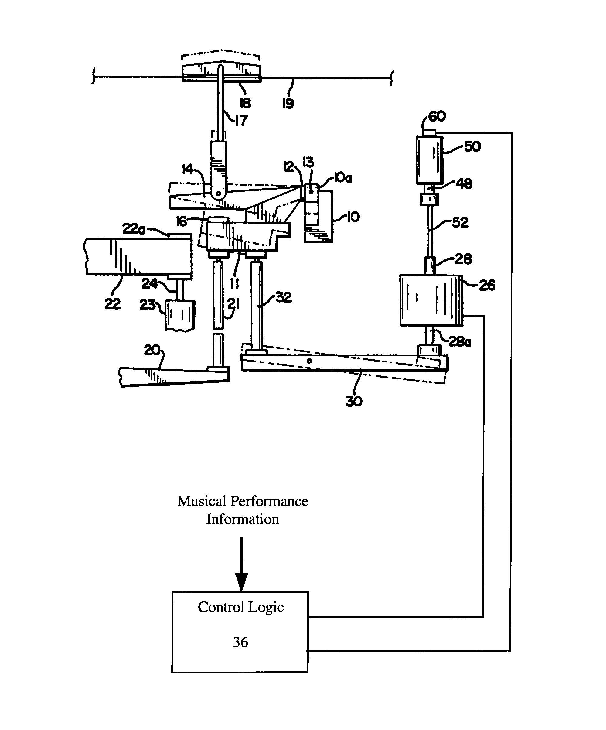
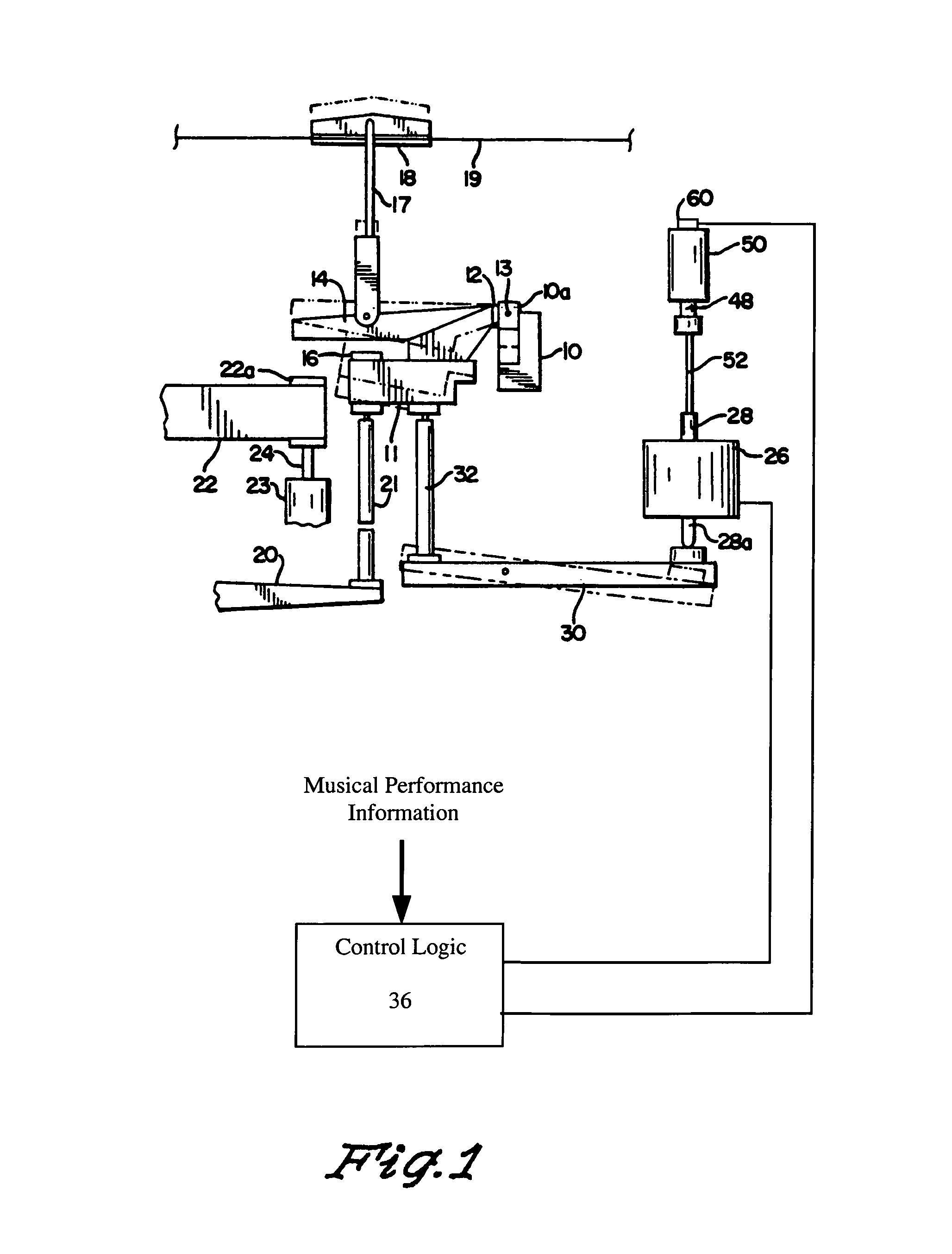
[0025]Embodiments of the invention provide systems and methods for driving one or more pedaling assemblies in a piano or other musical instrument. During playback of a musical performance, an actuator effects movement of a pedal mechanism. A sensor, such as a Hall-effect sensor, is used to provide information about the position of the pedal mechanism. The Hall-effect sensor does not directly measure the position of the pedal mechanism. Control logic uses the output of the Hall-effect sensor to calculate a desired drive, which is provided to the actuator.

[0026]Example embodiments will now be described in conjunction with the following figures.

[0027]In FIG. 1, there are illustrated several basic components of the pedal mechanism in a typical piano such as a grand piano. This particular view is a side view. Extending approximately the width of the piano is a fixed rail 10, having a hinge member 10a affixed thereto. In FIG. 1, only one such hinge member 10a is shown, however it will be ...


PUM


Abstract

A piano is equipped with an actuator that moves the piano pedal mechanism in a manner that reproduces the pedaling effects of an original performance with high accuracy. The actuator comprises a solenoid, a permanent magnet, a velocity sense coil, and a Hall-effect sensor. The Hall-effect sensor provides an indication of the displacement of the solenoid plunger in accordance with an inverse-square law. Closed-loop feedback control is provided to effect a very true reproduction of pedaling effects. Automatic calibration allows for simple installation.

Description

BACKGROUND OF THE INVENTION[0001]1. Field of the Invention[0002]The present invention relates to a system and method for controlling mechanically-driven musical instruments, and in particular to a system and method for controlling the pedaling of a mechanically-driven piano or other instrument.[0003]2. Background of the Technology[0004]Beginning with the invention of pneumatically-driven reproducing pianos in the early twentieth century, systems and methods have been developed for recording music played by a human pianist and for reproducing that music on a piano. In modern reproducing pianos, music played by a human pianist may be recorded on a recording medium such as a Compact Disc or the like, and the recorded music may be recreated, for example, using actuators to drive the keys and pedals of the piano. Many reproducing pianos have attempted to reproduce the subtle pedaling effects of the original performance.[0005]One way of controlling the pedals in a reproducing piano is des...

Claims


Application Information

Patent Timeline
Patent Type & Authority Patents(United States)
IPC IPC(8): G10H1/00
CPCG10H1/00G10F1/02G10F3/00G10H1/0041G10H1/348G10H2220/521G10H2230/011
Inventor STAHNKE, WAYNE, LEE
Owner STEINWAY & SONS
Why Eureka
Try Eureka