Method for reducing ripple noise of a display image

a display image and ripple noise technology, applied in the field of display image ripple noise reduction, can solve the problems of deteriorating image quality of lcd, and ripple noise that could be perceived by a user with naked eyes

Inactive Publication Date: 2014-04-01
CHUNGHWA PICTURE TUBES LTD
View PDF2 Cites 0 Cited by
  • Summary
  • Abstract
  • Description
  • Claims
  • Application Information

AI Technical Summary

Benefits of technology

[0013]Another object of the present invention is to resolve the flashover caused by using an inverter for applying a positive-potential and a negative-potential high voltage to adjacent lamps simultaneously.
[0014]For achieving objects mentioned above, one embodiment of the present invention provides a method for reducing ripple noise on a display image. The method comprises the following steps: (a) a first potential signal is supplied to a backlight module by an inverter; (b) the inverter is reset; (c) a second potential signal is supplied to the backlight by the inverter, wherein the first potential signal and the second potential signal have the same phase; and (d) the steps (b) to (c) are repeated. As such, since the first potential signal and the second potential signal have the same phase, the positions of the dark bands present in the image shown on the display panel would not change with time. Therefore, the dark bands would not be readily perceived by the user with naked eyes. In other words, the present method effectively reduces the ripple noise in the display image by improving the problem of the downward movement of the dark bands. In this embodiment, the inverter is coupled to a timing controller for resetting a timing sequence of the inverter, wherein the resetting step is performed during the transmission of the image to the display panel. Moreover, the backlight module of the present embodiment comprises a plurality of lamps, and each of the lamps receives the first and second potential signals from the inverter. For example, the first and second potential signals can be a sine wave signal.
[0015]In an alternative embodiment, the present invention provides a method for reducing the ripple noise on a display image. The method comprises the following steps: (a) a first potential signal is supplied to a backlight by an inverter; (b) the inverter is reset; (c) a second potential signal is supplied to the backlight by the inverter, wherein the phase difference between the first potential signal and the second potential signal is 180 degrees; (d) the inverter is reset again; and (e) the steps (a) to (d) are repeated. Consequently, the ripple noise present on the display would be effectively reduced by the alteration of the bright areas and dark areas on the display panel in conjunction with the persistence of vision of the user's eyes.
[0017]As discussed hereinabove, the present methods for reducing the ripple noise in the display image of the present invention may effectively reduce the ripple noise resulted from the interference caused by the high voltage outputted from the inverter to the backlight module. Besides, the conventional problem of the flashover may be avoided by not simultaneously outputting a positive-potential high voltage and a negative-potential high voltage to two adjacent lamps.

Problems solved by technology

As such, the signal transmitted from the inverter 101 through the backlight module 110 to the LCD panel would result in the ripple noise where an interference noise would be periodically generated on the display image.
Yet, when the images are displayed continuously, the dark band appeared to be moving downward, for example, the position of the dark band shifts from the dark band 210 to the dark band 211 shown in FIG. 2C, thereby resulting in the ripple noise that could be perceived by a user with naked eyes.
As such, the image quality of the LCD would be deteriorated.
However, the instant architecture is not able to effectively reduce the dark bands generated between the lamps 1111 and 1113 and between the lamps 1115 and 1117.
Moreover, during the startup of the lamps, the high voltage difference between the positive and negative potentials simultaneously generated by two adjacent lamps may cause the problem of flashover.
In view of the foregoing, the prior art fails to effectively reduce the ripple noise of a display image of the LCD panel caused by the driving inverter of the backlight module.
Therefore, the dark bands would not be readily perceived by the user with naked eyes.

Method used


Image

  • Method for reducing ripple noise of a display image
  • Method for reducing ripple noise of a display image
  • Method for reducing ripple noise of a display image

Examples


Embodiment Construction

[0027]The detailed description provided below in connection with the appended drawings is intended as a description of the preferred embodiments and is not intended to represent the only forms in which the present embodiments may be constructed or utilized. The description sets forth the functions of the example and the sequence of steps for constructing and operating the embodiments. However, the same or equivalent functions and sequences may be accomplished by different examples.

[0028]In accordance with common practice, the various described elements are not drawn to scale but are drawn to illustrate specific elements relevant to the present invention. Like reference numbers and designations in the various drawings indicate like elements.

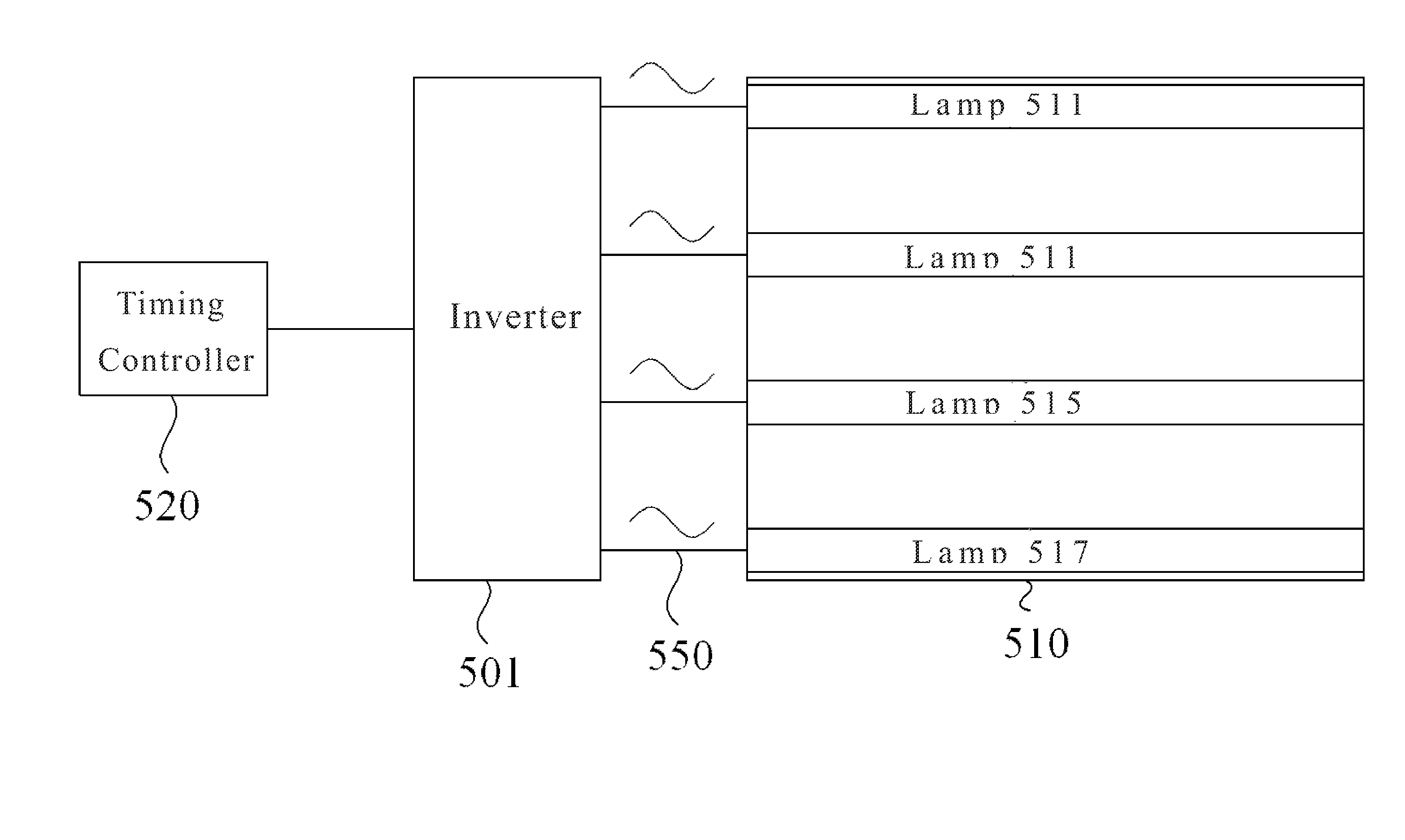
[0029]The present invention discloses a method for reducing the ripple noise on a display image by using a timing controller to reset an inverter while transmitting signal to the display panel in the aim to keep the potential of the backlight lamp...


PUM


Abstract

The present invention discloses a method for reducing ripple noise on the image of a display. The steps of the method include: (a) providing a first potential signal to a backlight module by an inverter; (b) resetting the inverter; (c) providing a second potential signal to the backlight by the inverter, wherein the phase difference between the first potential signal and the second potential signal is 180 degrees; (d) resetting again the inverter; and (e) repeating the steps (a) to (d) Consequently, the ripple noise present on the display would be effectively reduced by the alteration of the bright areas and dark areas on the display panel in conjunction with the persistence of vision of the user's eyes.

Description

CROSS-REFERENCE TO RELATED APPLICATION[0001]This present application claims priority to TAIWAN Patent Application Serial Number 099127632 filed on Aug. 18, 2010, which is herein incorporated by reference.TECHNICAL FIELD[0002]The present invention relates to a method for reducing ripple noise of the display image; in particular, a method of resetting an inverter by a timing controller during each signal transmission to the display panel so that the voltage of the backlight lamp is kept constant with time, thereby reducing the ripple noise present in the display image.BACKGROUND OF THE RELATED ART[0003]Traditionally, an LCD (Liquid Crystal Display) panel is illuminated by a backlight module for increasing the screen bright of the LCD panel to enhance the display quality.[0004]FIG. 1 illustrates a driving architecture of a backlight module of a conventional LCD. As shown in FIG. 1, an inverter 101 is used to supply a potential to each lamp 111, 113, 115 and 117 of the backlight module ...

Claims


Application Information

Patent Timeline
Patent Type & Authority Patents(United States)
IPC IPC(8): G09G5/10
CPCG09G3/3406G09G2310/08
Inventor HUANG, CHANG-XIN
Owner CHUNGHWA PICTURE TUBES LTD
Why Eureka
Try Eureka