Continuity tie for prefabricated shearwalls

a shearwall and continuous tie technology, applied in the field of shearwalls, can solve the problems of becoming more difficult to properly anchor shearwalls on the upper stories of buildings, and achieve the effects of increasing the cross-sectional area and ductility of the diaphragm, and improving the resistance of the shearwall to lateral forces

Active Publication Date: 2014-04-08
SIMPSON STRONG TIE
View PDF47 Cites 10 Cited by
  • Summary
  • Abstract
  • Description
  • Claims
  • Application Information

AI Technical Summary

Benefits of technology

[0008]In the preferred embodiment, the prefabricated shearwall includes a central diaphragm having a height generally defined by top and bottom edges, and a width generally defined by a pair of end sections. The diaphragm further includes at least one corrugation extending in the height direction at least partially between the top and bottom edges. The corrugation increases the cross-sectional area and ductility of the diaphragm in the lateral direction in comparison to conventional shearwalls, and further improves the resistance of the shearwall to lateral forces such as those generated in earthquakes, high winds, floods and snow loads.
[0009]In embodiments of the invention, the shearwall may further include a pair of reinforcing chords affixed to the end sections of the central diaphragm. The chords may be formed of nominal 2″×4″ wooden studs having a height equal to that of the central diaphragm. The chords further improve the resistance of the shearwall to lateral forces.
[0010]In order to distribute the significant compressive forces exerted by the shearwall over a large surface area on the underlying support surface, the shearwall further includes a flat sill plate affixed to the bottom edge of the central diaphragm. In embodiments of the invention, the sill plate may have a footprint at least equal to that of the central diaphragm, the chords and any sheathing affixed to the shearwall. The sill plate may be formed of a rigid material such as steel to evenly distribute any localized compressive forces from the shearwall. The sill plate may also underlie the chords to prevent any wetness or moisture from the underlying support surface from damaging the chords.
[0011]While a preferred embodiment of the invention includes a central diaphragm with a corrugation having a constant size and shape from the top edge to the bottom edge, the corrugation may be formed so that it is larger at the bottom edge of the central diaphragm and slopes inward to become smaller toward the top edge of the central diaphragm (or visa-versa). This results in a shearwall providing even greater lateral force resistance, as the sloped lines defined by the bends at the intersection between the various diaphragm sections have lateral components that exhibit increased resistance to movement in the lateral direction.

Problems solved by technology

When shearwalls are used on more than one story of a building, it becomes more difficult to properly anchor shearwalls on upper stories of a building.

Method used


Image

  • Continuity tie for prefabricated shearwalls
  • Continuity tie for prefabricated shearwalls
  • Continuity tie for prefabricated shearwalls

Examples


Embodiment Construction

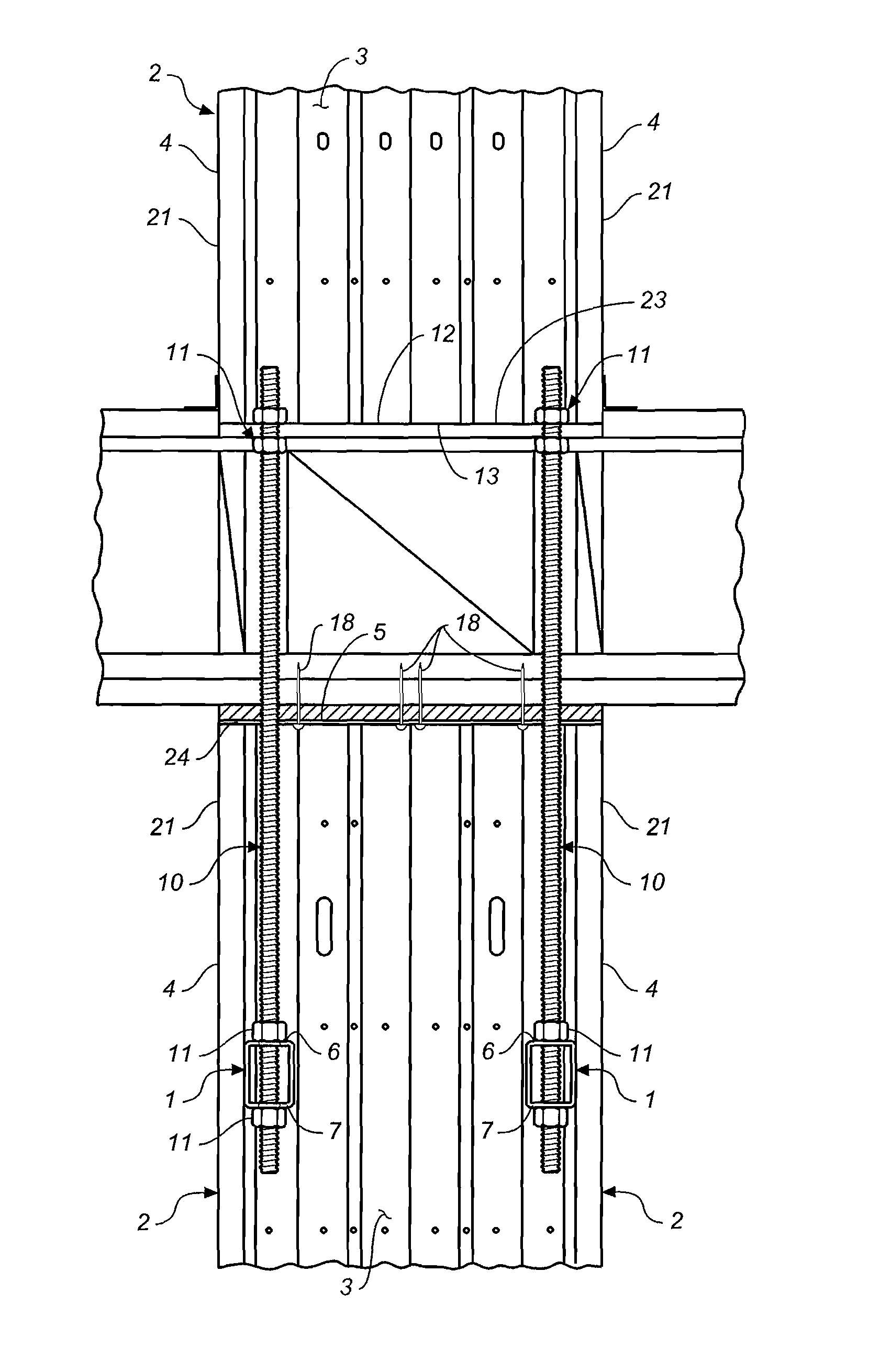
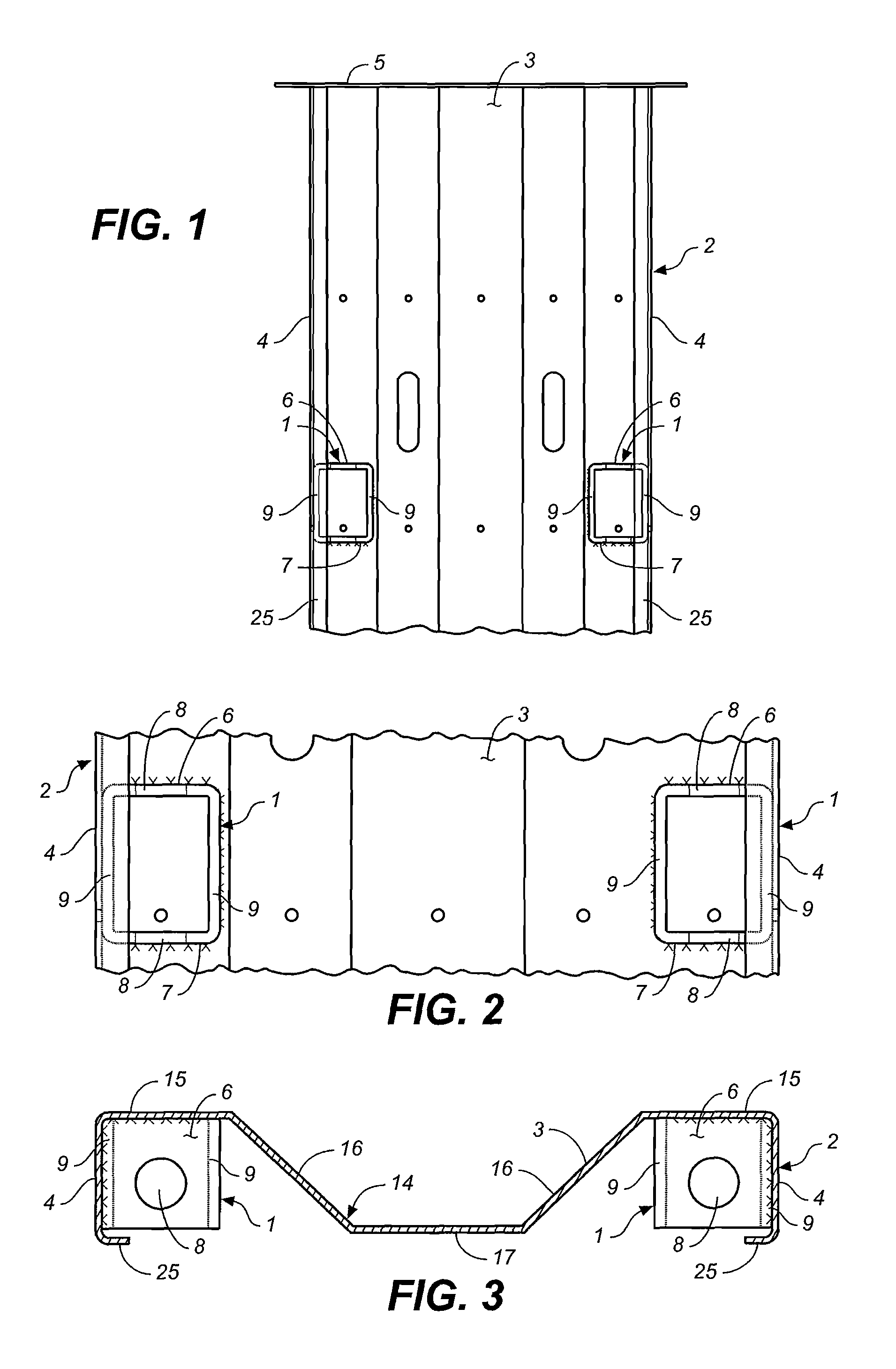
[0022]In the preferred embodiment, the present invention provides a continuity tie 1 attached to a prefabricated shearwall panel 2 including a central diaphragm 3 having a non-planar cross-section.

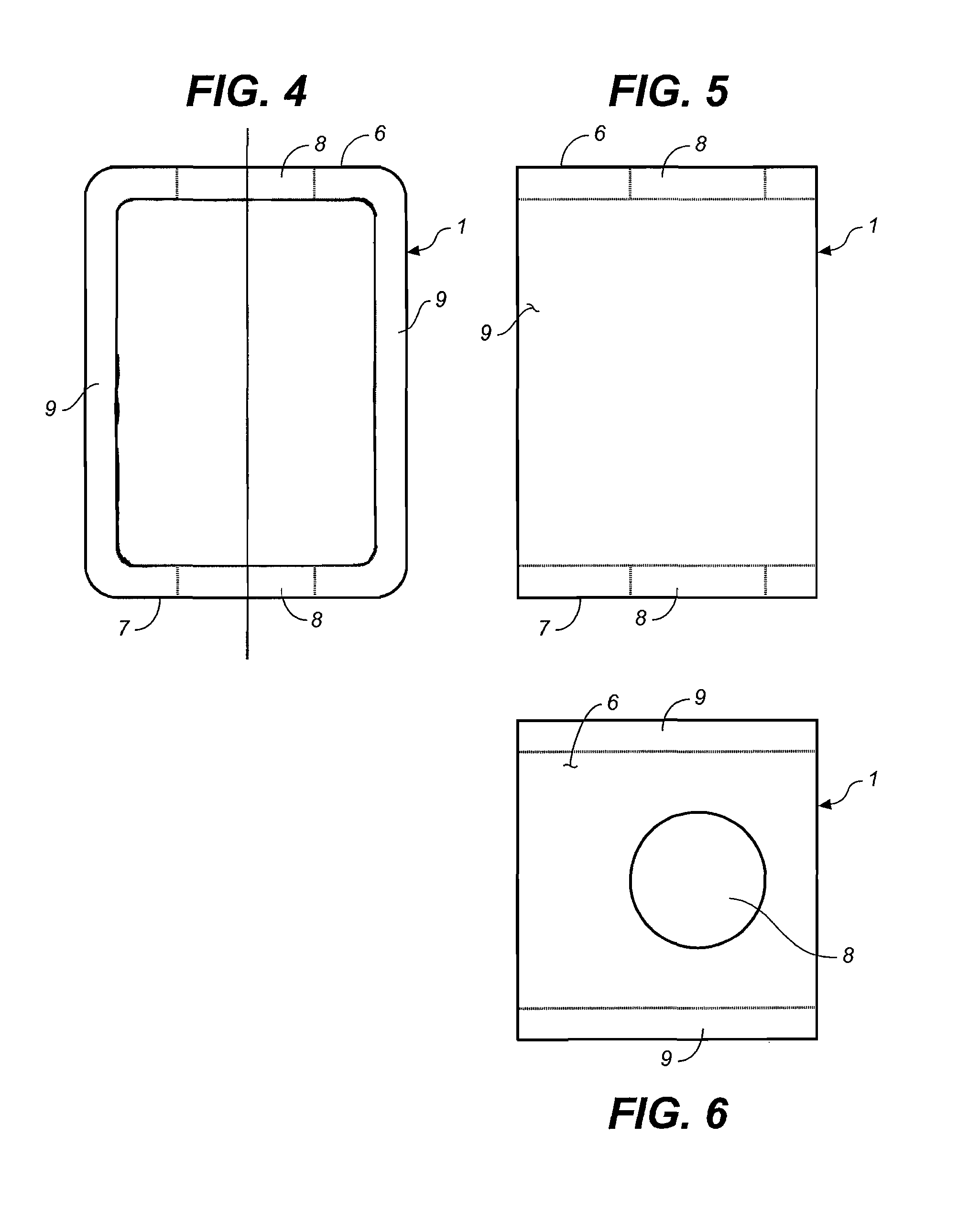
[0023]In the preferred embodiment, the continuity tie 1 is a tubular steel member welded to the sides or ends 4 and the diaphragm 3 of the prefabricated shearwall 2 near the top edge 5 of the shear wall 2. The continuity ties 1 are located near the top of the shearwall 2 to connect the upper portion of the shearwall 2 to a structural member, such as another prefabricated shearwall 2, disposed above the shearwall 2 with the inventive continuity ties 1. The tubular steel member is provided with a top surface 6 and a bottom surface 7. Substantially aligned openings 8 are provided in the top and bottom surfaces 6 and 7 of the tubular steel member. Side members 9 connect the top and bottom surfaces 6 and 7.

[0024]To connect the lower shearwall 2 to the upper structural member, in the preferred e...


PUM


Abstract

A continuity tie is provided for connecting a prefabricated shearwall to a structural member above the prefabricated shearwall. In the preferred embodiment, the continuity tie is a steel tube with aligned openings for receiving a threaded rod therethrough. The tube is welded to the shearwall. A pair of tubes are preferably attached. Nuts attach the threaded rod to the tube. The threaded rod attaches to a structural member above the tube.

Description

BACKGROUND OF THE INVENTION[0001]1. Field of the Invention[0002]The present invention relates to a shearwalls for opposing lateral forces on building walls, and in particular to a pair of prefabricated shearwalls, one disposed above the other, that are connected together by a pair of ties.[0003]2. Description of the Related Art[0004]Prefabricated shearwalls were developed to counteract the potentially devastating effects of natural phenomena such as seismic activity, high winds, floods and snow loads on the structural integrity of light-framed constructions.[0005]When shearwalls are used on more than one story of a building, it becomes more difficult to properly anchor shearwalls on upper stories of a building. The present invention provides a solution for anchoring an upper story shearwall or other structural member to a lower story shearwall or other structural member.SUMMARY OF THE INVENTION[0006]The present invention provides a shearwall having improved structures for anchoring ...

Claims


Application Information

Patent Timeline
Patent Type & Authority Patents(United States)
IPC IPC(8): E04B1/38E04C5/00
CPCE02D27/10
Inventor GRIDLEY, JERRY G.MONTAGUE, EMORYMCENTEE, PAULAREVALO, RICARDO
Owner SIMPSON STRONG TIE
Why Eureka
Try Eureka