Oil pump

a technology of oil pump and oil tank, which is applied in the direction of machines/engines, liquid fuel engines, and positive displacement liquid engines, etc., can solve the problems of increased oil temperature, increased cost, and wasted energy, and achieves low cost, reliable operation, and reduced control pressure

Inactive Publication Date: 2014-04-08
AISIN SEIKI KK
View PDF17 Cites 14 Cited by
  • Summary
  • Abstract
  • Description
  • Claims
  • Application Information

AI Technical Summary

Benefits of technology

[0018]An object of the present invention is to configure an oil pump at low cost that realizes highly reliable operation even at low temperatures, without a pointless flow of oil.
[0029]With this configuration, in a pressure region in which the oil pressure of the discharge port exceeds the third control value, the oil pressure of the discharge port acts on the tubular body irrespective of the state of the control valve, and causes the tubular body to move toward the side on which pump capacity decreases, enabling the pump capacity to be reduced and excess supply of oil to be suppressed.

Problems solved by technology

However, there is room for improvement, since a pointless and unnecessary flow of oil occurs when returning some or all of the oil from one of the discharge ports to the suction side, resulting not only wasted energy but also leading to a rise in oil temperature.
Also, with the oil pump described in Patent Document 2, there is room for improvement, since the electromagnetic valve has difficulty operating properly when the oil is highly viscous at low temperatures.
In particular, in the case where an electromagnetic valve is provided, there is room for improvement since electromagnetic valves are costly, and, moreover, an electrical control system for controlling the electromagnetic valve is required, leading to a rise in cost.
With the vane oil pumps described in Patent Document 3 and 4, there is room for improvement since electromagnetic valves are costly and an electrical control system for controlling the electromagnetic valve is also required, leading to a rise in manufacturing cost, in addition to the possibility of the electromagnetic valve having difficult operating properly when the oil is highly viscous at low temperatures, similarly to the oil pump described in Patent Document 2.

Method used


Image

  • Oil pump
  • Oil pump
  • Oil pump

Examples


first embodiment

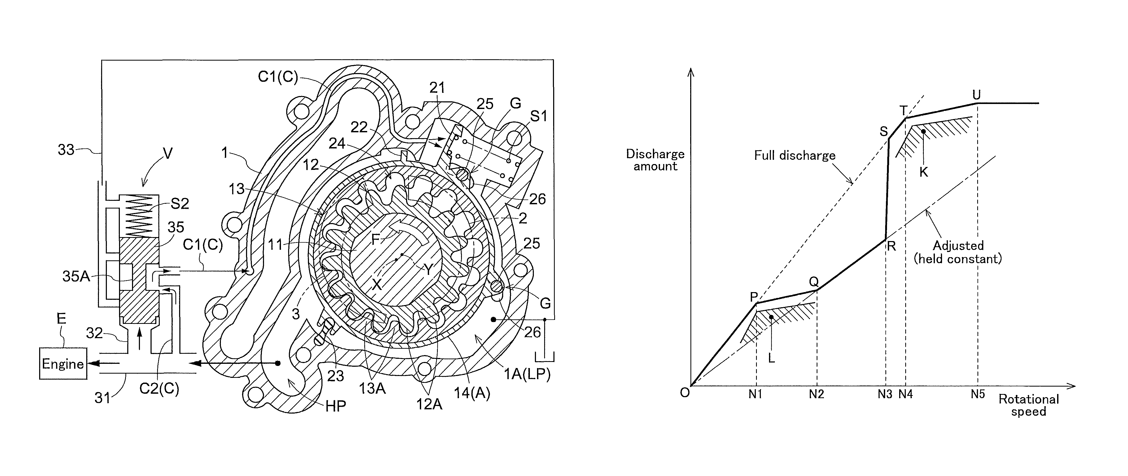
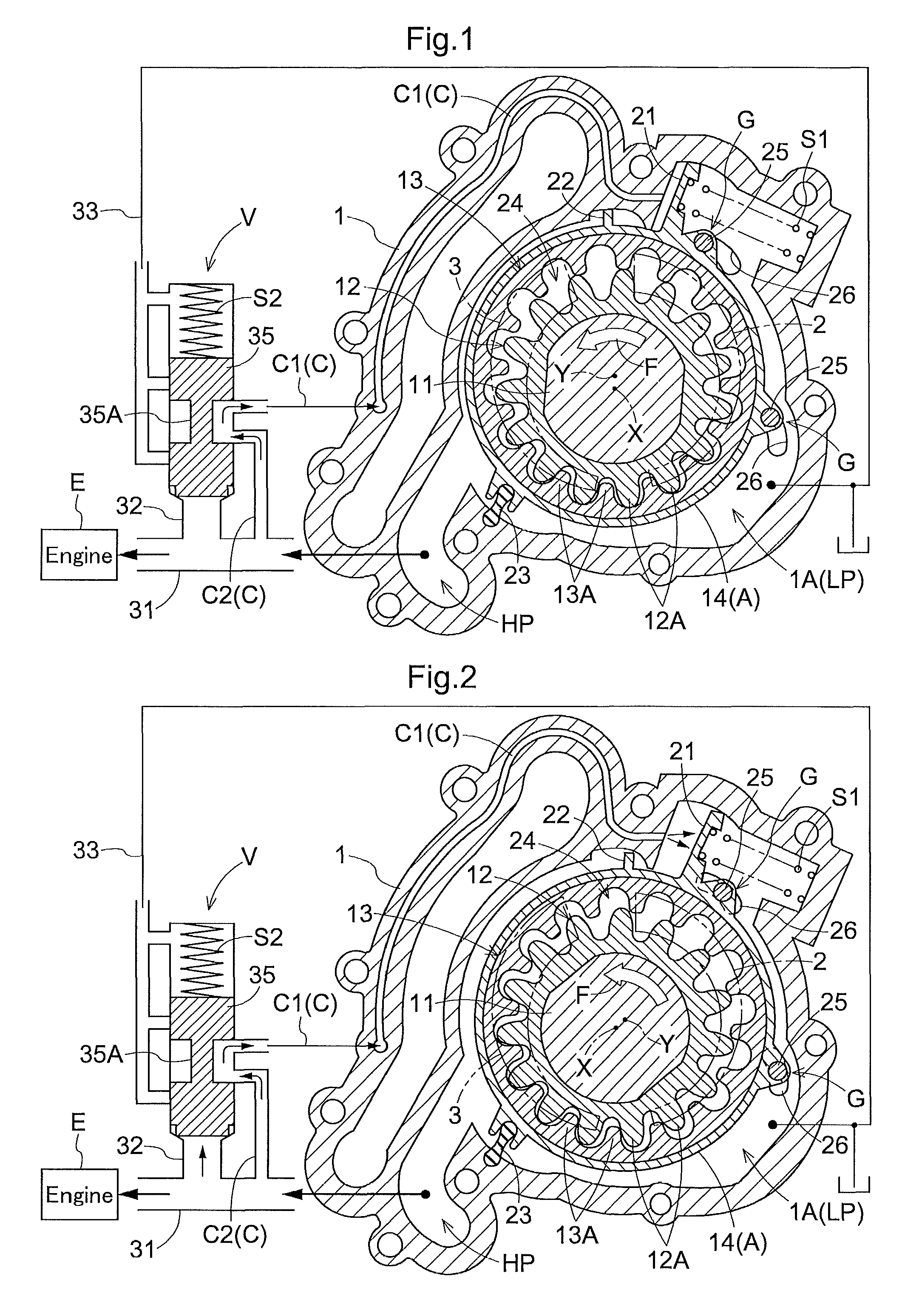
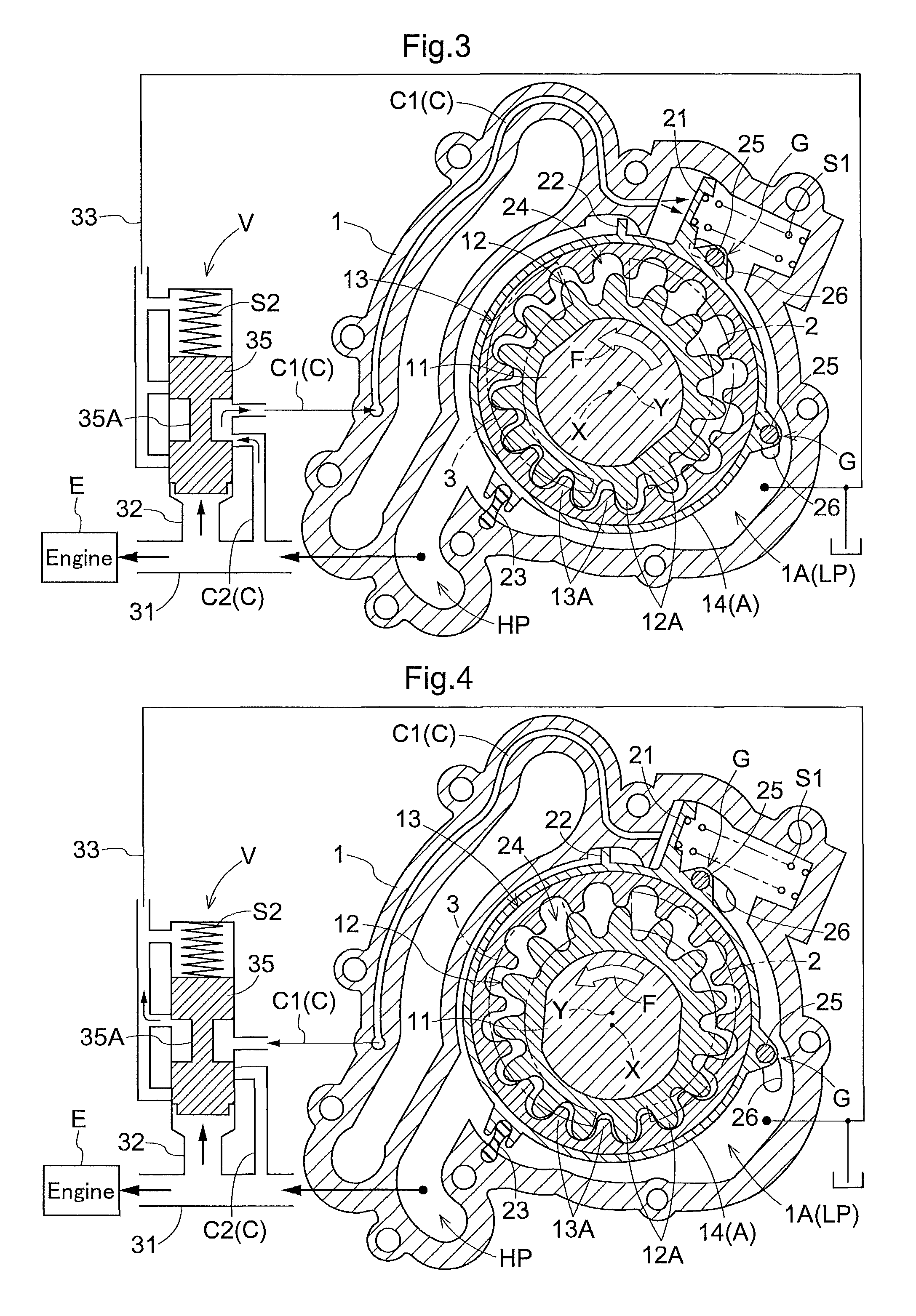
[0045]FIG. 1 shows a variable-capacity oil pump that is driven with an engine E of a vehicle so as to supply lubricating oil to the engine E and hydraulic oil of an oil pressure device provided in the engine E (lubricating oil and hydraulic oil will be collectively referred to as oil).

[0046]This oil pump is provided with an inner rotor (equivalent to the rotor of the present invention) 12 that is rotationally driven integrally with a drive shaft 11 about a drive rotation axis (equivalent to the rotation axis of the rotor of the present invention) X inside a casing 1, and an outer rotor (equivalent to the tubular body of the present invention) 13 that rotates about a driven rotation axis (equivalent to the tube axis of the present invention) Y that is eccentric to the drive rotation axis X, and is further provided with a capacity adjustment mechanism A that adjusts the pump capacity by causing the outer rotor 13 to revolve around the drive rotation axis X relative to the inner rotor ...

second embodiment

[0097]FIG. 9 and FIG. 10 show another embodiment of the oil pump according to the present invention.

[0098]The oil pump of the present embodiment is constituted by a variable-capacity vane oil pump.

[0099]This oil pump is provided with a rotor 12 having a plurality of movable vanes 4 in the circumferential direction that are biased so as to move projectably and retractably with respect to the outer circumferential side of the rotor, and a cam ring (equivalent to tubular body of the present invention) 13 that changes the amount of projection of the movable vanes 4 through a sliding action with the movable vanes 4.

[0100]The rotor 12 is coaxially provided with a cylindrical outer circumferential tube portion 12a that is rotationally driven integrally with a drive shaft 11 around a rotation axis X. On the inner circumferential side of the outer circumferential tube portion 12a is mounted a supporting ring 15 that supports the base end side of each movable vane 4.

[0101]The tip section of e...


PUM


Abstract

An oil pump includes a capacity adjustment mechanism that changes the pump capacity by moving a tubular body in a tube radial direction, with a pump chamber formed between the tubular body and an outer circumference side of a rotor, a first spring biasing the tubular body in a direction in which pump capacity increases, a control valve that converts oil pressure of the oil pump into control pressure and causes the control pressure to act on the capacity adjustment mechanism, and a second spring biasing a valve body in order to set the control pressure in the control valve. The relationship of the biasing forces of the first and second springs is set so that pump capacity is set to maximum when the engine rotational speed is less than a predetermined value, and so that pump capacity is reduced when the engine rotational speed exceeds a predetermined value.

Description

TECHNICAL FIELD[0001]The present invention relates to oil pumps, and more particularly to improving variable-capacity oil pumps.BACKGROUND ART[0002]As an oil pump configured as mentioned above, Patent Document 1 discloses a configuration that has a drive gear (exemplary rotor) that is rotationally driven by an engine and an internal tooth driven gear (exemplary tubular body) that meshes with the drive gear, and is provided with a single suction port, two discharge ports, and an oil pressure control valve that controls the flow of oil from the two discharge ports.[0003]In Patent Document 1, the oil pressure control valve is provided with a valve body that controls the flow of hydraulic oil from one of the discharge ports, and a spring that causes a biasing force to act on the valve body. With this oil pump, when the engine rotational speed is low, hydraulic oil from the two discharge ports is merged and pumped out. Then, when the rotational speed of the engine increases, excess suppl...

Claims


Application Information

Patent Timeline
Patent Type & Authority Patents(United States)
IPC IPC(8): F04C14/22F04B49/00
CPCF04C2/102F04C14/26F04C2/00F04C2/086F04C14/226
Inventor ONO, HISASHIKAZAOKA, SHINJI
Owner AISIN SEIKI KK
Why Eureka
Try Eureka