Braided prosthetic sockets with attachment plates and methods of manufacture

a technology of attachment plates and prosthetic sockets, which is applied in the field of braided prosthetic sockets with attachment plates and methods of manufacture, can solve the problems of laborious, reduce the production time and cost of prosthetics relative to conventional methods, etc., and achieves the effects of convenient retrieval and use, strong and light weight, and convenient us

Inactive Publication Date: 2014-04-08
MENTIS SCI
View PDF10 Cites 36 Cited by
  • Summary
  • Abstract
  • Description
  • Claims
  • Application Information

AI Technical Summary

Benefits of technology

[0014]This invention provides new above knee (AK) and below the knee (BK) prosthetic sockets and implements specific manufacturing processes for the production of prosthetic sockets through the automated, computer controlled bi-axial and tri-axial braiding of sockets, over a mold or mandrel made of carved foam, plaster or thermoset material in the conventional manner, but also of an easily retrievable and usable wax or water soluble casting material created by a Computer Aided Design (CAD) file on a Numerically Controlled (CNC) machine tool. The CAD file is created from a 3-D digital image of the patient's residual limb generated by a laser scanner or other sensing mechanism. This method of manufacture using aerospace fibers such as graphite or Kevlar, and high performance resins, is used to create a socket which is stronger and lighter weight than conventionally manufactured sockets, and generates a very accurate negative replica of the patient's residual limb, thus adding to the comfort of the patient. Braiding also allows incorporation of woven cloth and reinforcements into the braiding process for added strength at selected areas, for example, where cut outs may be desired or appliances added to the base socket structure. The method also dramatically decreases the production time and cost of the prosthetic relative to conventional methods, which are very labor intensive. The CAD file can be retained for future use in the generation of additional sockets which may be needed to replace lost or broken sockets
[0015]The manufacturing process described in this invention, the production of sockets through automated, computer controlled bi-axial or tri-axial braiding of the new sockets, circumvents many of the drawbacks in conventional production cycles cited above. As will be seen in the description of the invention, the braiding process is initiated over a mold or mandrel which could be made conventionally with a plaster or thermoset mold or as described in the current invention by an easily retrievable and re-usable wax or water soluble casting material. The wax mold, created by a CAD file on a CNC machine can dramatically decrease the production time and cost.
[0016]The sockets produced in this manner by the textile braiding process are stronger and lighter weight. The lighter weight especially benefits the patient, since weight of the prosthetic is often linked to other secondary effects like hip problems induced by heavy prosthetic limbs. The automation of the braiding process as described in this invention allows the operator to “engineer” the socket during the production process, by varying the lay down of fiber or fiber tow on the mandrel by adjusting the speed of the gantry and braider to open up and / or close the braid, thus adjusting the angle between the fibers or tows. This affects the fiber density which is also adjustable, depending on the strength requirements of the socket. By regulating the tension on the fibers, the operator is also able to achieve a more compact weave of fibers. This has an additional beneficial effect, from a cost and weight point of view, of requiring less resin.

Problems solved by technology

The method also dramatically decreases the production time and cost of the prosthetic relative to conventional methods, which are very labor intensive.

Method used


Image

  • Braided prosthetic sockets with attachment plates and methods of manufacture
  • Braided prosthetic sockets with attachment plates and methods of manufacture
  • Braided prosthetic sockets with attachment plates and methods of manufacture

Examples


Embodiment Construction

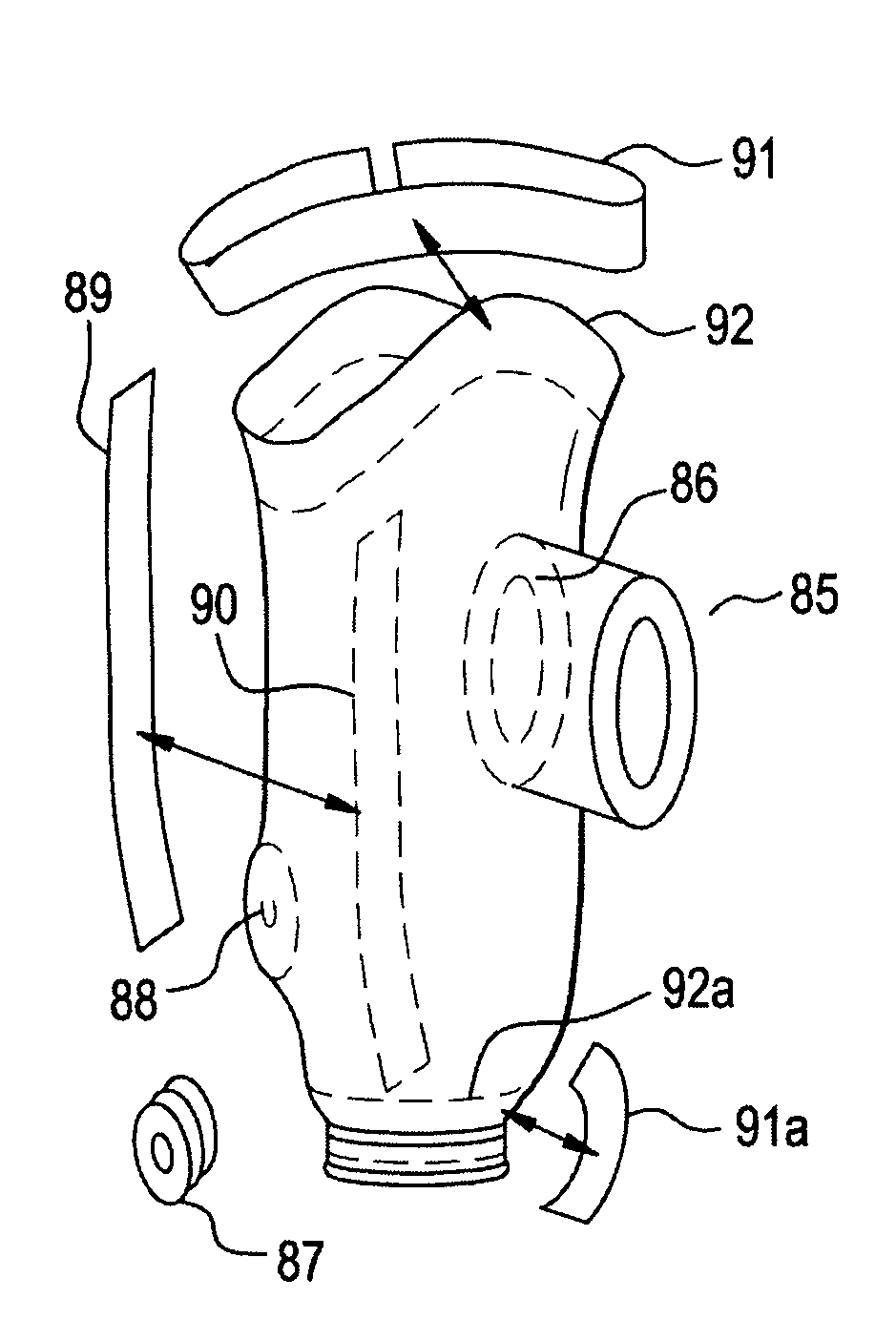
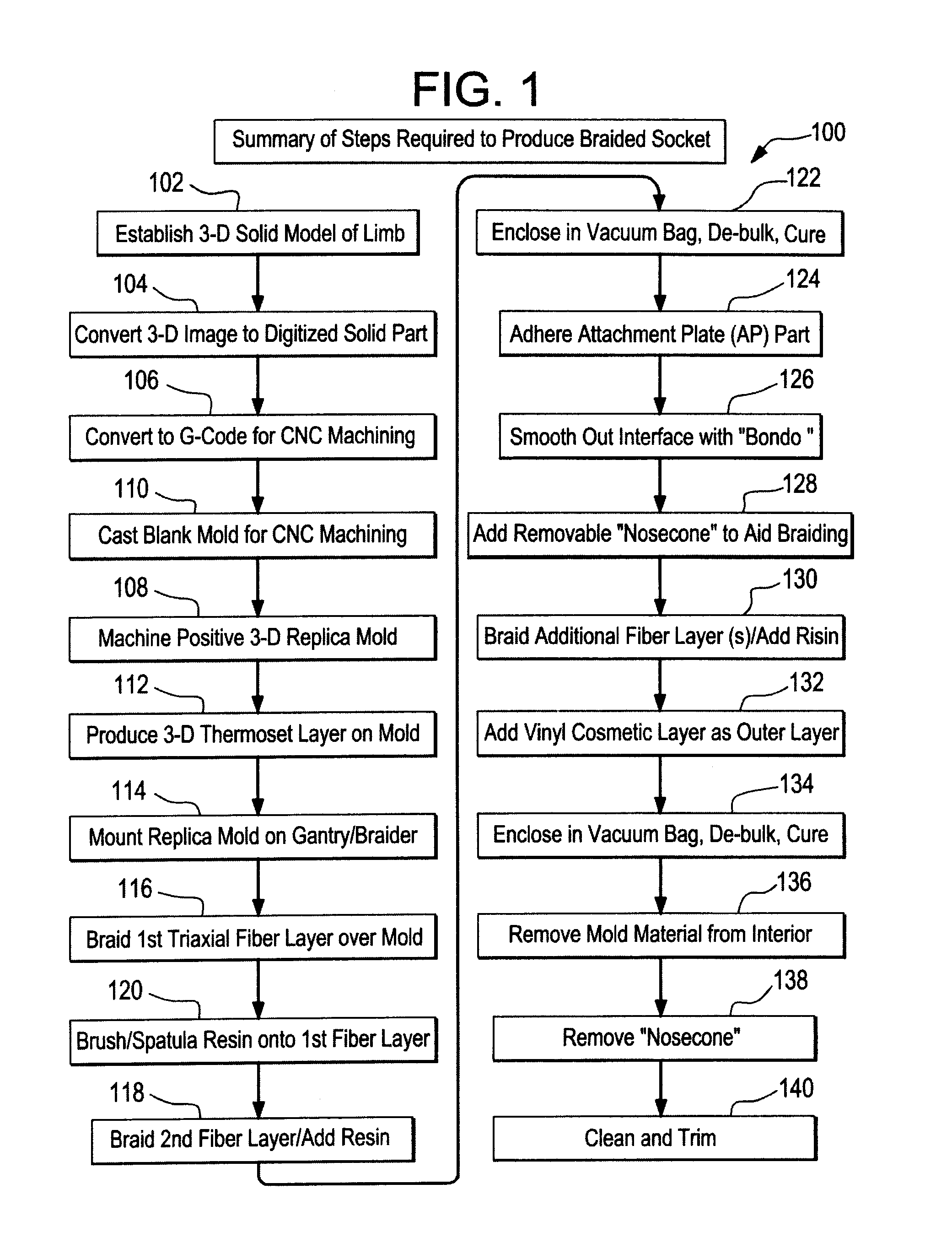
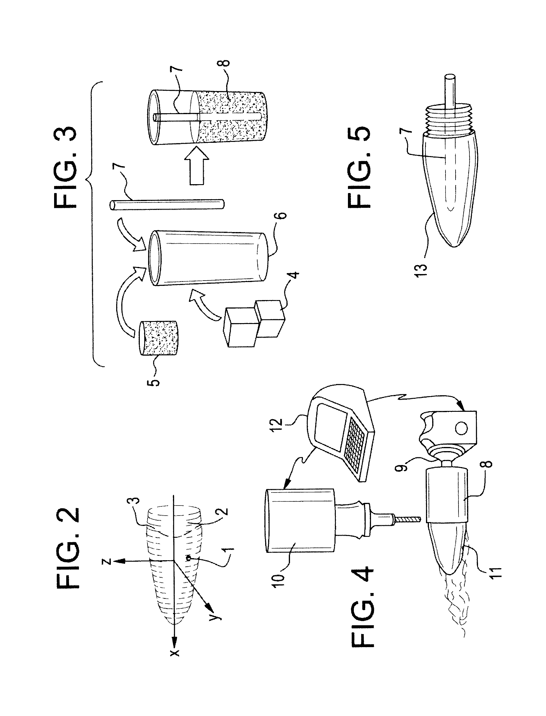
[0051]FIG. 1 illustrates the step-by-step process for the fabrication of the braided socket 100 with an attachment plate, beginning with the 3-D solid model 102 of the residual limb, which is converted to a digital solid part file 104, and then to G-code 106, which controls the milling machine fabrication 108 of a positive replica of the residual limb from the cast blank mold 110. A thin thermoplastic layer is produced on the mold 112 which can strengthen the mold during the braiding process and create a smooth inner surface in the final product. The replica mold is then attached to the gantry 114, which inserts the mold mandrel into the braider, where layers of fiber are laid down 116. The resin is applied manually 120 between layers 116, 118 by brush, spatula or spray, and the assembly is then vacuum bagged, de-bulked and cured 122. An attachment plate is affixed 124 to the distal end of the cured assembly. The interface between the socket and the attachment plate is smoothed 126 ...


PUM

PropertyMeasurementUnit
shapeaaaaaaaaaa
reducing pressureaaaaaaaaaa
weightaaaaaaaaaa

Abstract

This invention provides new above knee (AK) and below the knee (BK) prosthetic sockets and implements specific manufacturing processes for the production of prosthetic sockets through the automated, computer controlled bi-axial and tri-axial braiding of sockets, over a mold or mandrel made of carved foam, plaster material or wax that is a replica of the patient's truncated limb, and is created by a Computer Aided Design (CAD) file controlling a Numerically Controlled (CNC) machine tool. This method of manufacture using aerospace fibers such as graphite or Kevlar, and high performance resins, is used to create a socket which is stronger and lighter weight than conventionally manufactured sockets. Braiding also allows incorporation of woven cloth, tapes and other reinforcements into the braiding process for added strength at selected areas. The method dramatically decreases the production time and cost of the prosthetic relative to conventional methods.

Description

[0001]This application claims the benefit of U.S. Provisional Application No. 61 / 423,212, filed Dec. 15, 2010, which is hereby incorporated by reference in its entirety as if fully set forth herein.BACKGROUND OF THE INVENTION[0002]1. Field of the Invention[0003]The present invention relates to processes related to the manufacture of above the knee and below the knee prosthetic sockets using aerospace quality fibers, resins, and textile braiding techniques to produce lighter weight, stronger, lower cost prosthetic products relative to conventional production methods.[0004]2. Description of the Prior Art[0005]Currently, production of trans-tibial and trans-femoral prosthetic sockets starts with the creation of a cast of the patient's residual limb using plaster of Paris wraps or bandages to map the shape of the residual limb. After the wrap has hardened, it is carefully removed and is used as a mold for the casting of a positive plaster mold, a replica of the residual limb, with a pip...

Claims


Application Information

Patent Timeline
Patent Type & Authority Patents(United States)
IPC IPC(8): A61F2/80D04C1/06
CPCA61F2002/505B29L2031/7532D04C1/02B29C70/443B29K2105/0845D04C3/48B29C70/222A61F2002/5053B29K2105/0827A61F2002/5055D10B2505/02A61F2002/5001A61F2/80A61F2/5046
Inventor DIGNAM, JOHN J.MATE, BRADLEY J.ANDERSON, CHRISTOPHER S.MCDERMOTT, PATRICK P.
Owner MENTIS SCI
Why Eureka
Try Eureka