Anaerobic waste treatment apparatus

a waste treatment and anaerobic technology, applied in biological water/sewage treatment, filtration separation, separation processes, etc., can solve the problems of increasing the overall cost of producing an organic waste treatment apparatus, prolonging the time it takes to treat organic waste, slow growth of bacteria, etc., to reduce the upfront cost, the effect of reducing the overall cos

Inactive Publication Date: 2014-04-08
J U B ENGINEERS
View PDF24 Cites 0 Cited by
  • Summary
  • Abstract
  • Description
  • Claims
  • Application Information

AI Technical Summary

Benefits of technology

[0011]Embodiments of the present invention relate to apparatuses and methods configured to create a cost-efficient waste treatment and / or energy production system that is capable of producing energy comparable to conventional waste treatment apparatuses, but with reduced costs. In particular, example embodiments relate to an anaerobic waste treatment apparatus that includes a container and at least two zones of bio-film media that are disposed within the container. In some cases, the apparatus has lowered upfront cost as one or more of the layers in the container are efficiently arranged by randomly orienting bio-film media. In one example, the bio-film media includes tires and the container is a dug out portion of earth. Moreover, the waste treatment apparatus may additionally comprise a waste pump that is coupled to a waste pipe and configured to introduce untreated, partially treated, new, or recycled waste into the container at one or more locations.

Problems solved by technology

Recently, however, organic waste treatment has become more popular as a mechanism for generating energy due at least in part to the volatile cost of traditional energy sources.
Unfortunately, bacteria growth can be a slow process, thus prolonging the time it takes to treat organic waste and create the methane gas which can subsequently be used to create energy.
Notably, however, the highly organized arrangements of bio-film media generally require a significant amount of construction time, leading to a higher overall cost to produce an organic waste treatment apparatus.
The higher upfront cost limits the economic viability of organic waste treatment by provoking energy producers and consumers to choose traditional energy sources instead of investing in the organic waste treatment infrastructure.
However, a smaller waste treatment apparatus reduces the amount of energy that the waste treatment apparatus is capable of producing, again making a waste treatment apparatus a potentially less commercially viable energy solution relative to other energy options.

Method used


Image

  • Anaerobic waste treatment apparatus
  • Anaerobic waste treatment apparatus
  • Anaerobic waste treatment apparatus

Examples


Embodiment Construction

[0029]The present invention may be embodied in other specific forms without departing from its spirit or essential characteristics. The described embodiments are to be considered in all respects only as illustrative and not restrictive. The scope of the invention is, therefore, indicated by the appended claims rather than by the foregoing description. All changes which come within the meaning and range of equivalency of the claims are to be embraced within their scope.

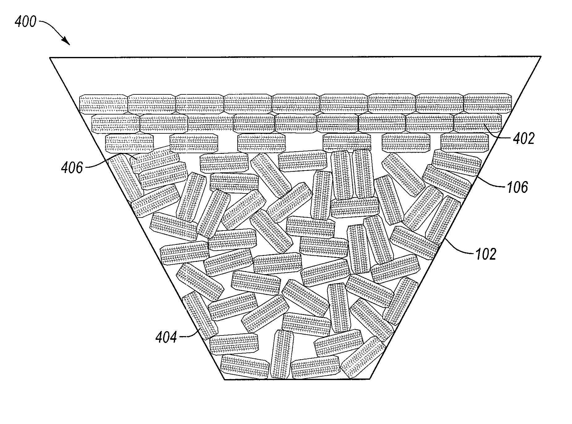
[0030]Embodiments of the invention relate to energy generation, a waste treatment apparatus, arrangements of bio-film media within a waste treatment apparatus, and methods of arranging bio-film media within a waste treatment apparatus.

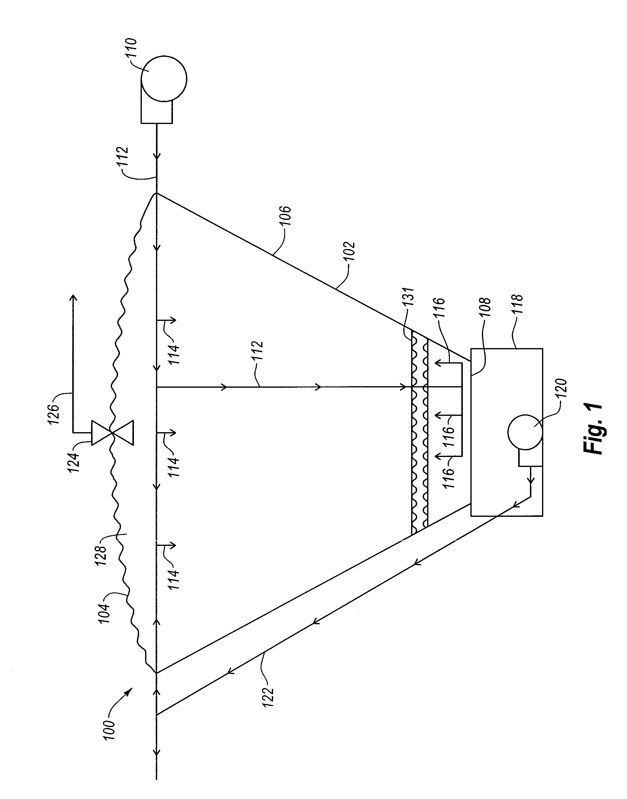
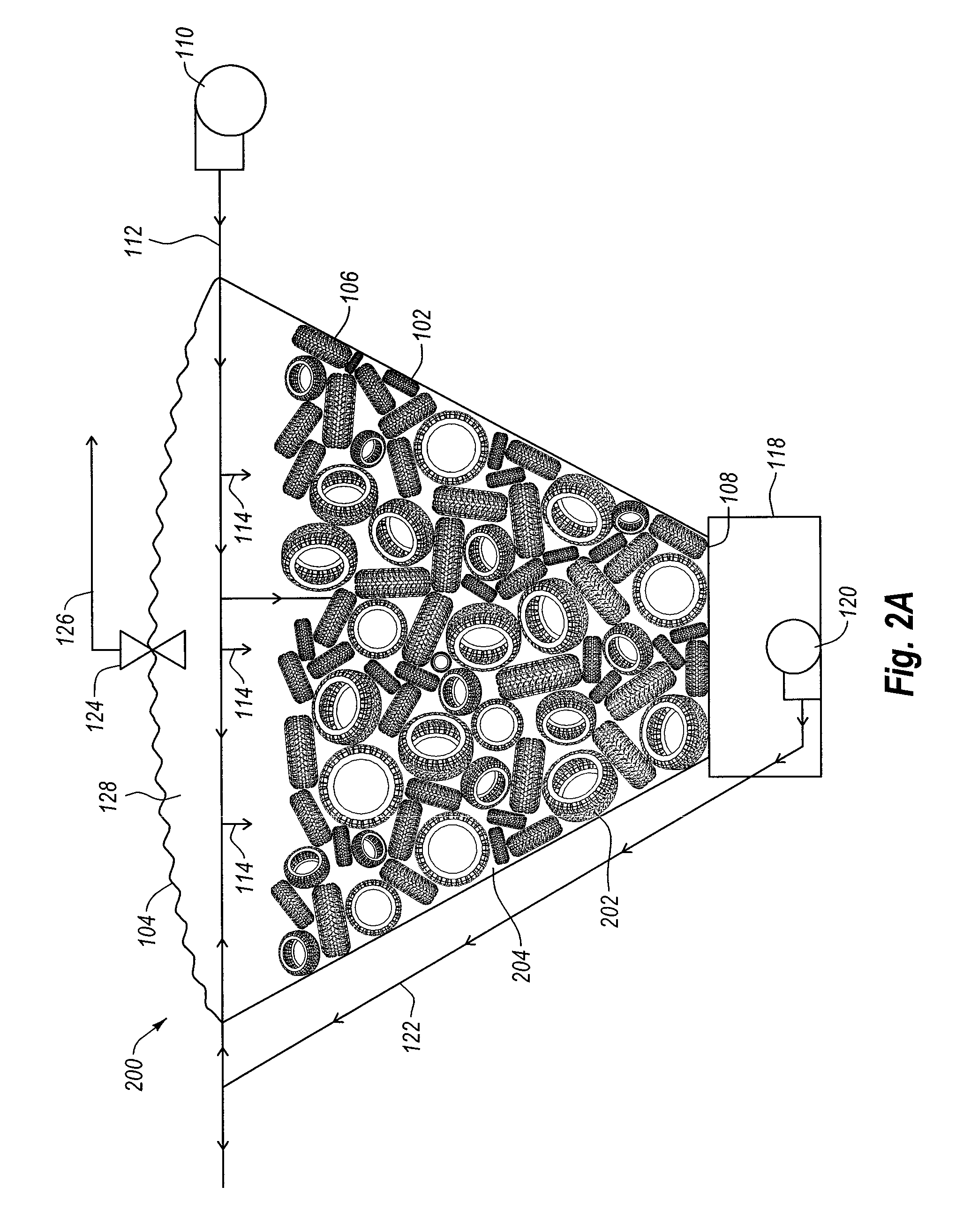
1. Example Embodiments of a Waste Treatment Apparatus and Gas Production System

[0031]Now turning to FIG. 1, an example embodiment of a waste treatment apparatus 100 is illustrated. As shown in FIG. 1, the example waste treatment apparatus 100 includes a container 102. In some cases, conta...


PUM

PropertyMeasurementUnit
temperatureaaaaaaaaaa

Abstract

An anaerobic waste treatment apparatus comprises a container wherein randomly oriented bio-film media are disposed. An example waste treatment apparatus includes a container and optionally has at least two zones of bio-film media that are disposed within the container. In one example, the bio-film media includes torus-shaped materials, or other materials with voids therein, and the container is a dug out portion of earth. Moreover, the anaerobic waste treatment apparatus may additionally comprise a waste pump that is coupled to a waste pipe and configured to introduce waste into the container at one or more locations. When two zones are included, one zone may be randomly oriented, while a proximate zone may be substantially horizontal and / or an organized zone. The random zone may also have a transition layer thereon that supports the organized zone or that provides an interface between the organized and random zones.

Description

CROSS-REFERENCE TO RELATED APPLICATIONS[0001]This application claims the benefit of, and priority to, U.S. Application Ser. No. 61 / 266,904, filed on Dec. 4, 2009 and entitled “WASTE TREATMENT APPARATUS,” which application is expressly incorporated herein by this reference in its entirety.BACKGROUND[0002]1. The Field of the Invention[0003]The present application generally relates to waste treatment and gas production. More particularly, the present application relates to an organic waste treatment apparatus, and more particularly still to arranging of bio-film media within a waste treatment apparatus, a method of creating the arrangement of bio-film media, and the production of gas using the waste treatment apparatus.[0004]2. Background and Related Art[0005]The treatment of organic waste has been implemented for many years. Recently, however, organic waste treatment has become more popular as a mechanism for generating energy due at least in part to the volatile cost of traditional e...

Claims


Application Information

Patent Timeline
Patent Type & Authority Patents(United States)
IPC IPC(8): C02F3/28
CPCC02F3/2826C02F2303/10C02F3/109Y02W10/12Y02W10/15Y02W10/30Y10T29/49826Y02W10/10
Inventor GREEN, TROY, M.
Owner J U B ENGINEERS
Why Eureka
Try Eureka