Optical module, method of producing optical module, optical transmission module, and electronic apparatus

a technology of optical modules and optical transmission modules, applied in the field of optical modules, can solve the problems of prominent induced, difficulty in aligning the optical element and the optical waveguide with respect to each other with high accuracy, etc., and achieve the effects of reducing the diffusion of light, preventing the curing contraction of the sealing agent, and increasing the optical coupling efficiency

Inactive Publication Date: 2014-04-15
ORMON CORP
View PDF10 Cites 1 Cited by
  • Summary
  • Abstract
  • Description
  • Claims
  • Application Information

AI Technical Summary

Benefits of technology

[0015]An optical module according to one or more embodiments of the present invention enables alignment of an optical waveguide and an optical element with respect to each other with high accuracy and also enables suppressing the optical loss at the optical coupling of the optical waveguide and the optical element to each other.
[0018]With the aforementioned structure, the sealing agent can be embedded in most of the gap between the optical transmission path and the optical element. This can reduce the diffusion of light between the optical transmission path and the optical element and, this effect can increase the optical coupling efficiency.
[0019]Further, since a gap is provided between the emission surface or the incidence surface of the optical transmission path and the surface of the sealing agent on the light receiving surface or the light emitting surface of the optical element, the surface of the optical transmission path which is faced to the optical element does not contact with the sealing agent. This prevents the curing contraction of the sealing agent from affecting the optical transmission path. This can realize excellent alignment accuracy in adhering and securing the optical transmission path to the support board.

Problems solved by technology

However, with the aforementioned structures in the Patent Documents 1 and 2, there is difficulty in aligning the optical element and the optical waveguide with respect to each other with high accuracy, due to the wettability and the curing contraction of the resin embedded in the gap between the light emitting device and the optical waveguide.
Particularly, in cases where the optical waveguide 101 is a film optical waveguide with high flexibility, the aforementioned problem is prominently induced.

Method used


Image

  • Optical module, method of producing optical module, optical transmission module, and electronic apparatus
  • Optical module, method of producing optical module, optical transmission module, and electronic apparatus
  • Optical module, method of producing optical module, optical transmission module, and electronic apparatus

Examples


Embodiment Construction

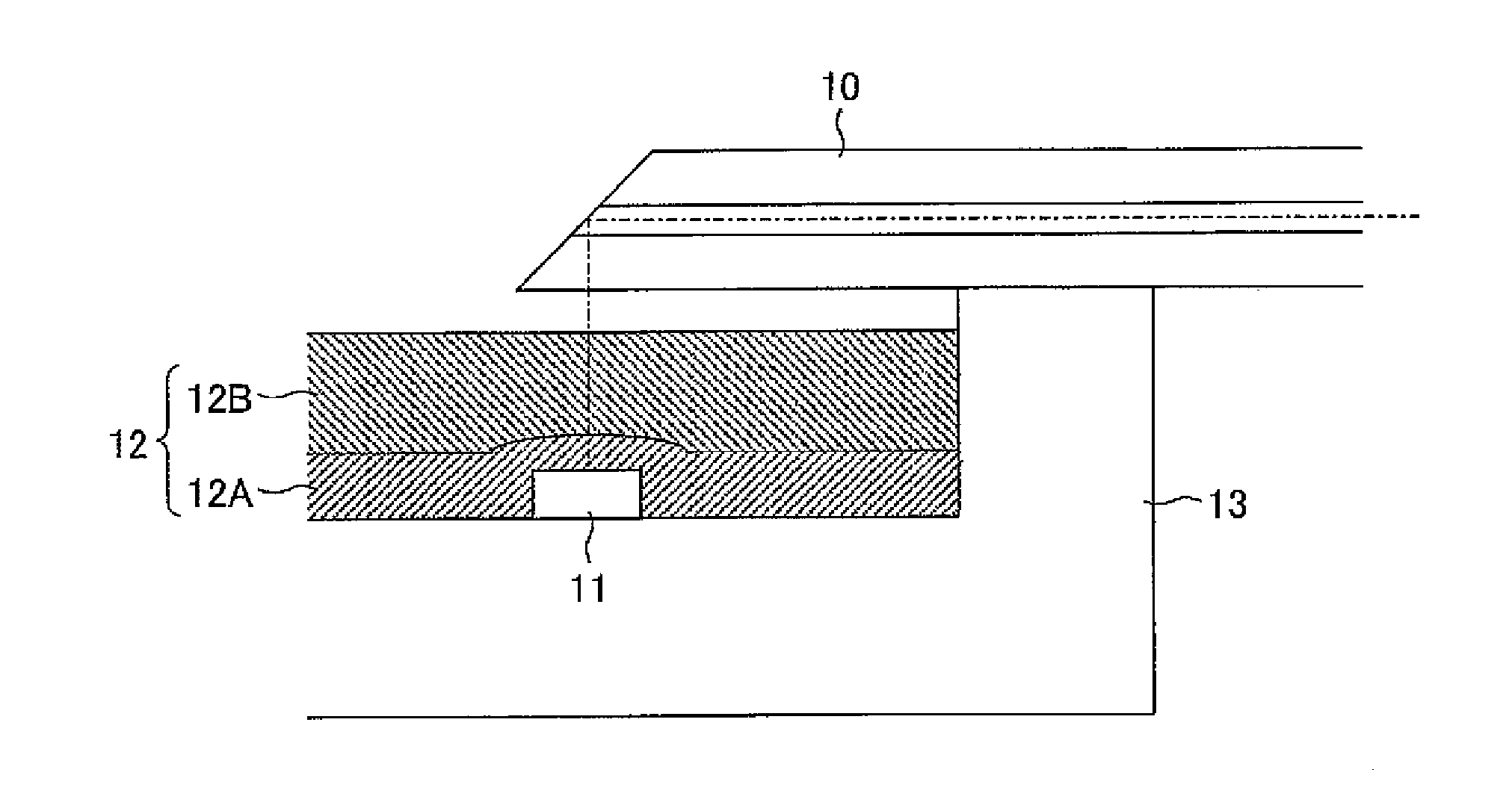
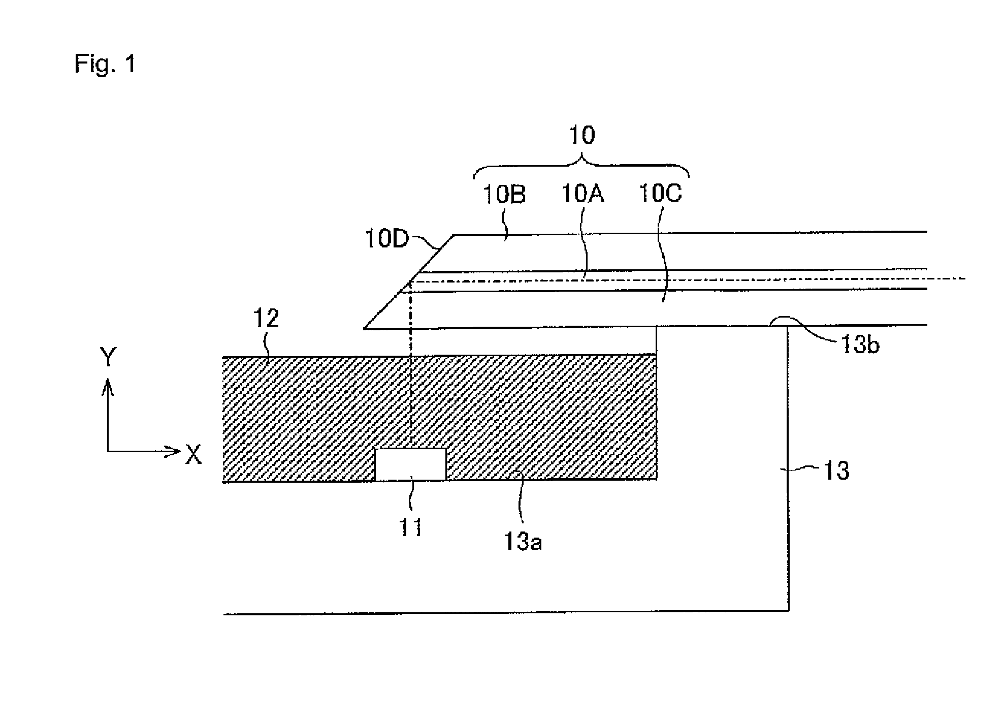
[0044]Hereinafter, an embodiment of the present invention will be described with reference to the drawings. At first, an exemplary structure of an optical module according to the present embodiment will be described, with reference to FIG. 1.

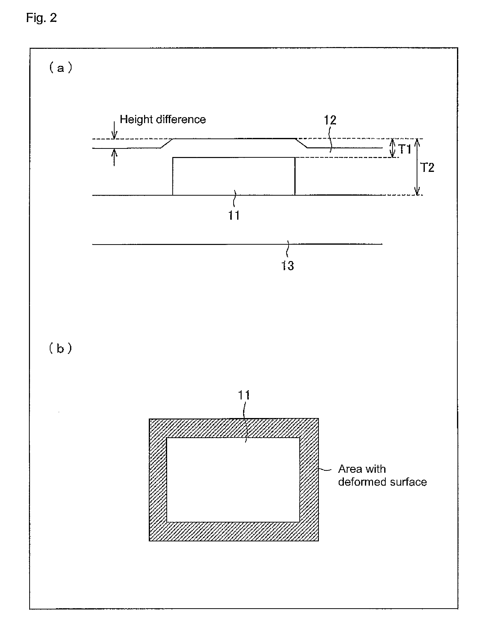
[0045]The optical module 1 illustrated in FIG. 1 is structured to include an optical transmission path 10, an optical element 11, a sealing agent 12 and a support board 13, in general, near an end portion thereof. Further, in the following description, an optical waveguide 10 is employed as the optical transmission path, and a sealing resin 12 is employed as the sealing agent. The optical waveguide 10 is secured at its end portion to the support board 13 through adhesion or the like, in a state where the relative positional relationship between the end portion of the optical waveguide 10 and the optical element 11 is fixed. The optical module 1 may further include electric wirings and electric connection portions for facilitating extraction of e...


PUM

PropertyMeasurementUnit
refractive indexaaaaaaaaaa
angle of inclinationaaaaaaaaaa

Abstract

An optical module has a support board, an optical transmission path, and at least a single optical element having a light receiving function or a light emitting function provided on the support board. A light emission surface of the optical transmission path or a light incidence surface of the optical transmission path is arranged such that the optical element and the optical transmission path are optically coupled to each other, with respect to a light receiving surface or a light emitting surface of the optical element. The optical element is sealed by a sealing agent. A gap is provided between the optical transmission path and the surface of the sealing agent on the light receiving surface or the light emitting surface of the optical element.

Description

TECHNICAL FIELD[0001]The present invention relates to an optical module for optical data transmission and, more particularly, relates to an optical transmission module including a flexible optical transmission path and a method for producing the same.BACKGROUND ART[0002]In recent years, there have been extended optical communication networks capable of high-speed and large-capacity data communication. Such optical communication networks are expected to be mounted on commercial apparatuses, in the future. Therefore, there has been a need for optical data transmission cables (optical cables) for electrical inputting and outputting which are usable in the same ways as those of existing electric cables, as applications for realizing high-speed and large-capacity data transmission, countermeasures against noises and data transmission among boards in apparatuses. It is desirable that film optical waveguides are employed as such optical cables, in consideration of flexibility.[0003]An opti...

Claims


Application Information

Patent Timeline
Patent Type & Authority Patents(United States)
IPC IPC(8): G02B6/42G02B6/36H01L33/48
CPCG02B6/4214G02B6/4253G02B6/4255G02B6/42
Inventor SANO, AKIHIKONOZAWA, HIROTOOKUNO, TOSHIAKITANAKA, JUNICHIYASUDA, NARUHOSOKAWA, HAYAMI
Owner ORMON CORP
Why Eureka
Try Eureka