Diverter disc

a technology of diverter discs and discs, applied in the direction of conveyors, instruments, material analysis, etc., can solve the problems of inflexible arrangement, unnecessary cost of each stop, and needing additional space, so as to improve the performance of the system, reduce the contact surface further, and high contact pressure

Active Publication Date: 2014-04-22
FLEXLINK COMPONENTS
View PDF17 Cites 4 Cited by
  • Summary
  • Abstract
  • Description
  • Claims
  • Application Information

AI Technical Summary

Benefits of technology

[0017]By this first embodiment of the diverter disc according to the invention, the diverter disc is able to hold the slide ring of a puck in a firm grip during the diversion of the puck. This is achieved in that the discrete contact points exhibit a relatively small contact surface, which in turn will provide a relatively high contact pressure between the slide ring and the discrete contact points. The slide ring can rotate freely on the puck and is adapted to let the puck rotate relative the slide ring when the puck is diverted by a diverter disc. Because the diverter disc will grip the puck at the slide ring, the diversion will not require as much power as when conventional pucks are diverted by a conventional diverter disc, since the diverter disc and the puck will be able to move relative each other. This will improve the performance of the system.
[0018]In an advantageous development of the invention, the grip opening is provided with protrusions which will decrease the contact surface further.
[0019]This will improve the performance of the system further, since the contact pressure between the slide ring of a puck and the discrete contact points of the grip opening will be increased.

Problems solved by technology

Such an arrangement is not very flexible and is mostly used when all objects are to be manipulated in the same manner, and when the manipulation requires only a short time duration.
Each stop is however an unnecessary cost and it also requires additional space.
In a large system having several work stations, the total power requirement will thus be unnecessarily high.
These solutions work fine in some systems, but are anyhow subjected to the above mentioned problem.

Method used


Image

  • Diverter disc
  • Diverter disc
  • Diverter disc

Examples


Embodiment Construction

[0028]The embodiments of the invention with further developments described in the following are to be regarded only as examples and are in no way to limit the scope of the protection provided by the patent claims.

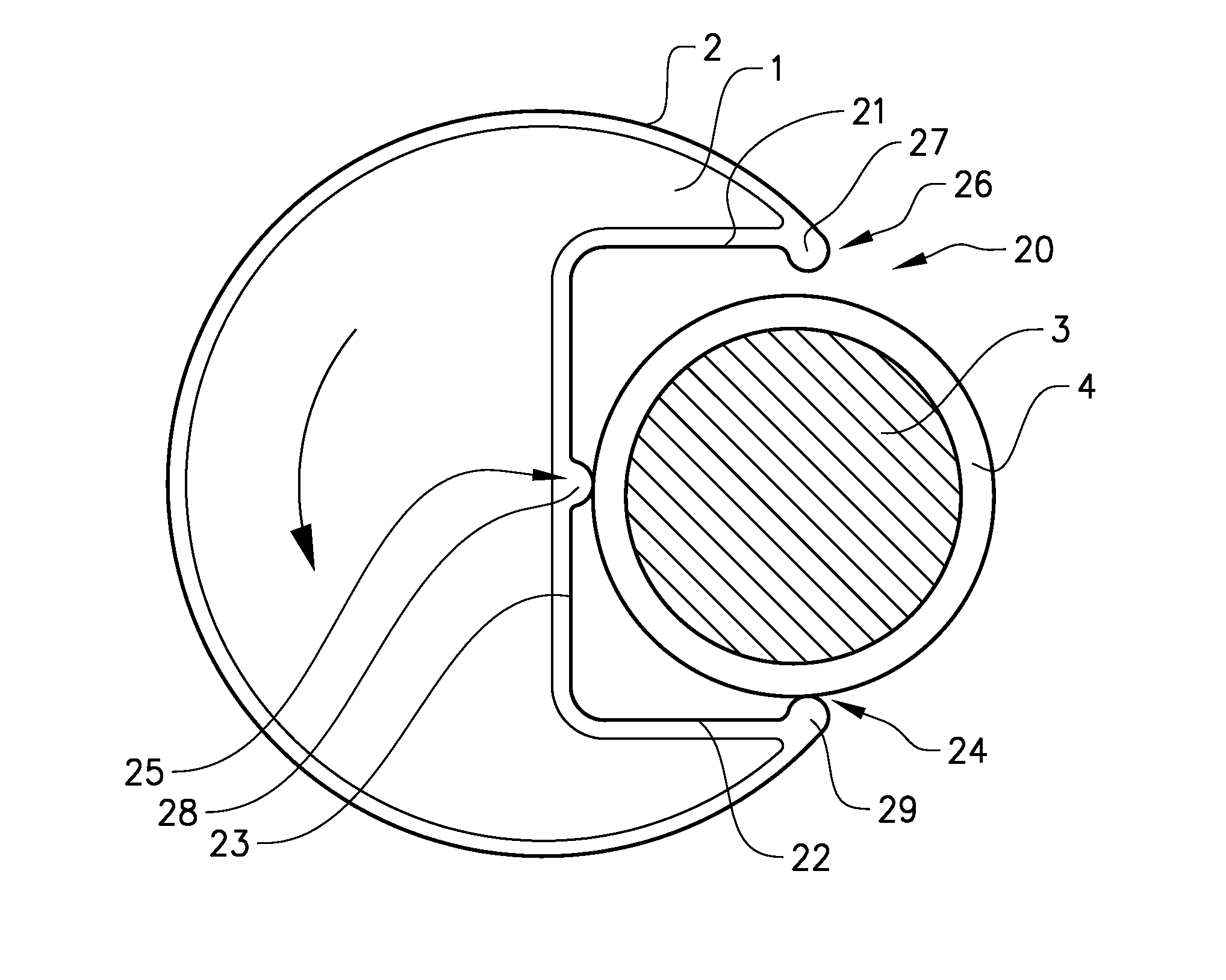
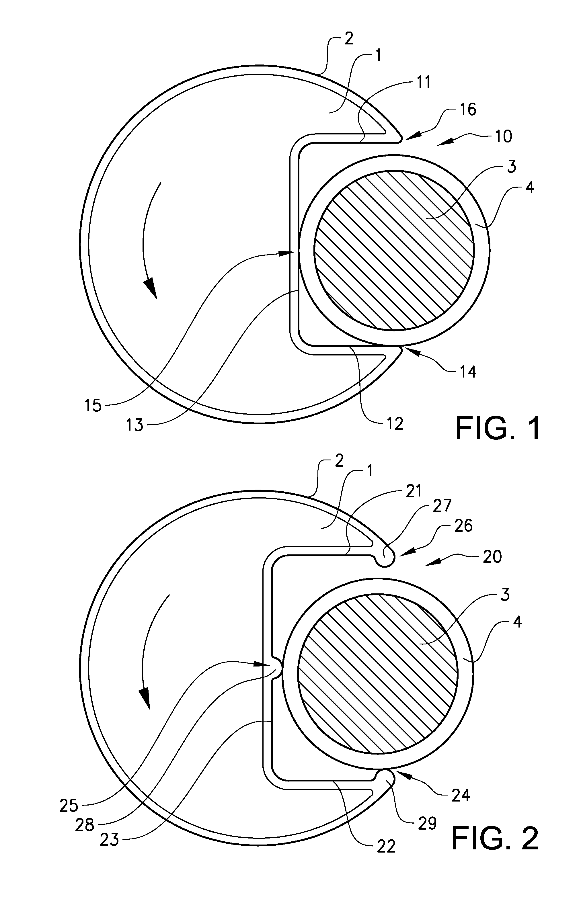
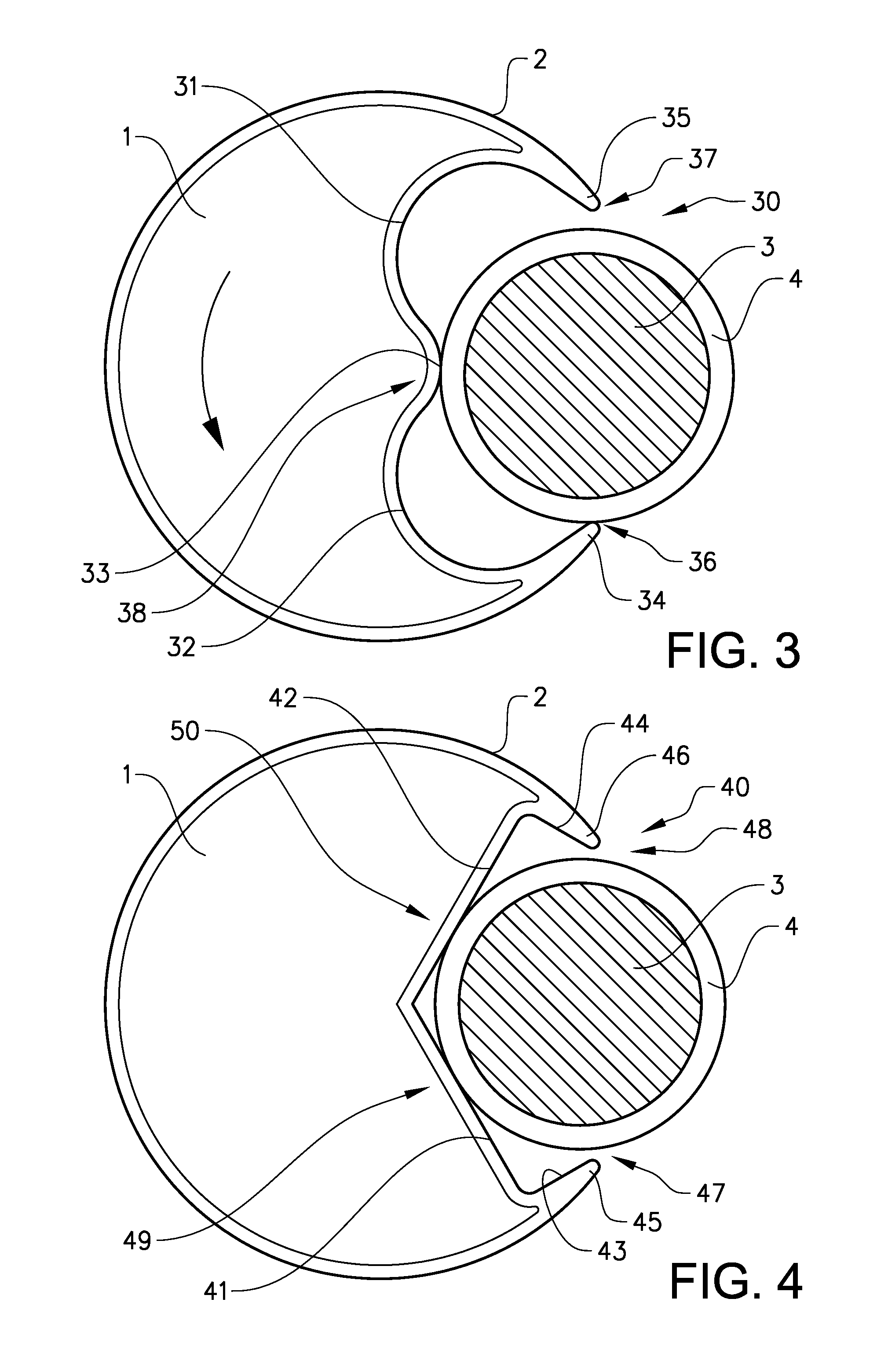
[0029]FIG. 1 shows a first embodiment of a diverter disc according to the invention. The diverter disc is mainly adapted to be used with pucks having a slide ring in the contact region between the grip opening and the puck, where the diverter disc holds the puck. It is however also possible to use the diverter disc with conventional pucks, even though a conventional puck will not make use of the advantages of the inventive diverter disc. The diverter disc is adapted to be used in a conveyor system comprising a conveyor track on which the pucks are transported. The conveyor track may be either a chain conveyor or may comprise vertical, horizontal or round belts. The diverter disc is used to divert a puck from a first conveyor track into another conveyor track or to divert a ...


PUM


Abstract

Diverter disc for a conveyer system, comprising a circular outer periphery and an grip opening formed in the periphery of the diverter disc, where the grip opening is adapted to hold and divert a puck comprising a circular slide ring at the contact region and that the grip opening is shaped in a non circular shape such that a plurality of discrete contact points are formed in the grip opening. The advantage of the diverter disc is that it will be able to hold the slide ring of a puck in a more secure way due to the reduced contact surface compared with a conventional diverter disc.

Description

RELATED APPLICATIONS[0001]This application is a US National Stage application filed under 35 U.S.C. §371 from International Application Serial No. PCT / SE2011 / 051422, filed Nov. 24, 2011 and published as WO 2012 / 071008 A1 on May 31, 2012, which claims the priority benefit of Sweden Patent Application No.: 1051242-4, filed on Nov. 26, 2010, the contents of which applications and publication are incorporated herein by reference in their entirety.TECHNICAL FIELD[0002]The present invention relates to a diverter disc having an opening adapted for a carrier puck comprising a slide ring. The diverter disc is adapted to be used in a conveyor system.BACKGROUND ART[0003]Conveying devices, such as those which are used for moving objects between different stations in a factory, usually comprise a conveying track in the form of a belt or a chain. The conveying tracks can be recessed in a trench with vertical side surfaces. Alternatively, they can be located on the horizontal upper surfaces of the...

Claims


Application Information

Patent Timeline
Patent Type & Authority Patents(United States)
IPC IPC(8): B65G47/46
CPCB65G47/82B65G47/763G01N2035/0467B65G47/71B65G17/00B65G47/51B65G47/52B65G47/84G01N35/04B65G47/846B65G2812/02613
Inventor ABBESTAM, GORANANG.LANDER, KLAS
Owner FLEXLINK COMPONENTS
Why Eureka
Try Eureka