Projector

a projector and projector body technology, applied in the field of projectors, can solve the problems of increasing reducing the size of the projector, and affecting the efficiency of the projector, so as to reduce the obstacles to wireless communication and efficient cooling

Active Publication Date: 2014-04-22
SEIKO EPSON CORP
View PDF5 Cites 0 Cited by
  • Summary
  • Abstract
  • Description
  • Claims
  • Application Information

AI Technical Summary

Benefits of technology

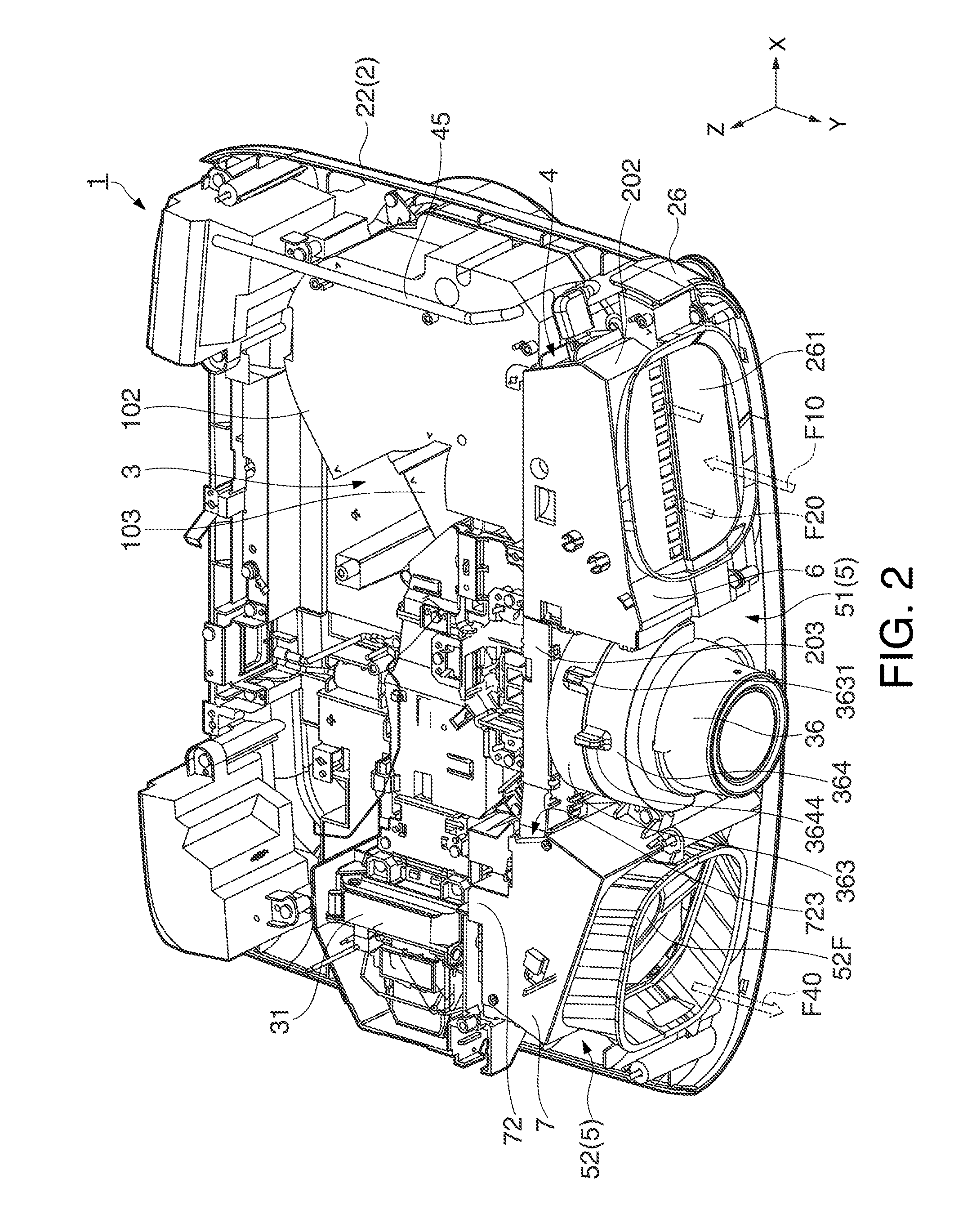
[0009]According to this configuration, the projector has the first channel and the second channel. The first channel guides the air introduced through the inlet port toward the light modulation device by the drive of the first fan, while the second channel guides the air introduced into the external housing toward the second fan via the second controller by the drive of the second fan. The second fan discharges the air within the external housing through the outlet port. According to this arrangement, the air flowing along the first channel and the air flowing along the second channel do not interfere with each other. In this case, control over the flow amount and the flow speed of the air supplied toward the first channel and the second channel for cooling the light modulation device and the second controller becomes easier, contributing to efficient cooling for the light modulation device and the second controller. Accordingly, deterioration of a projected image, deterioration of the predetermined function of the second controller, and deterioration of the peripheral components around the light modulation device and the second controller can be reduced. Moreover, the efficient cooling thus achieved further allows reduction of the sizes of the first fan and the second fan and therefore the entire size of the projector, and also allows the use of the first fan and the second fan capable of supplying larger amounts of air so as to reduce noise generated from the projector.Application Example 2
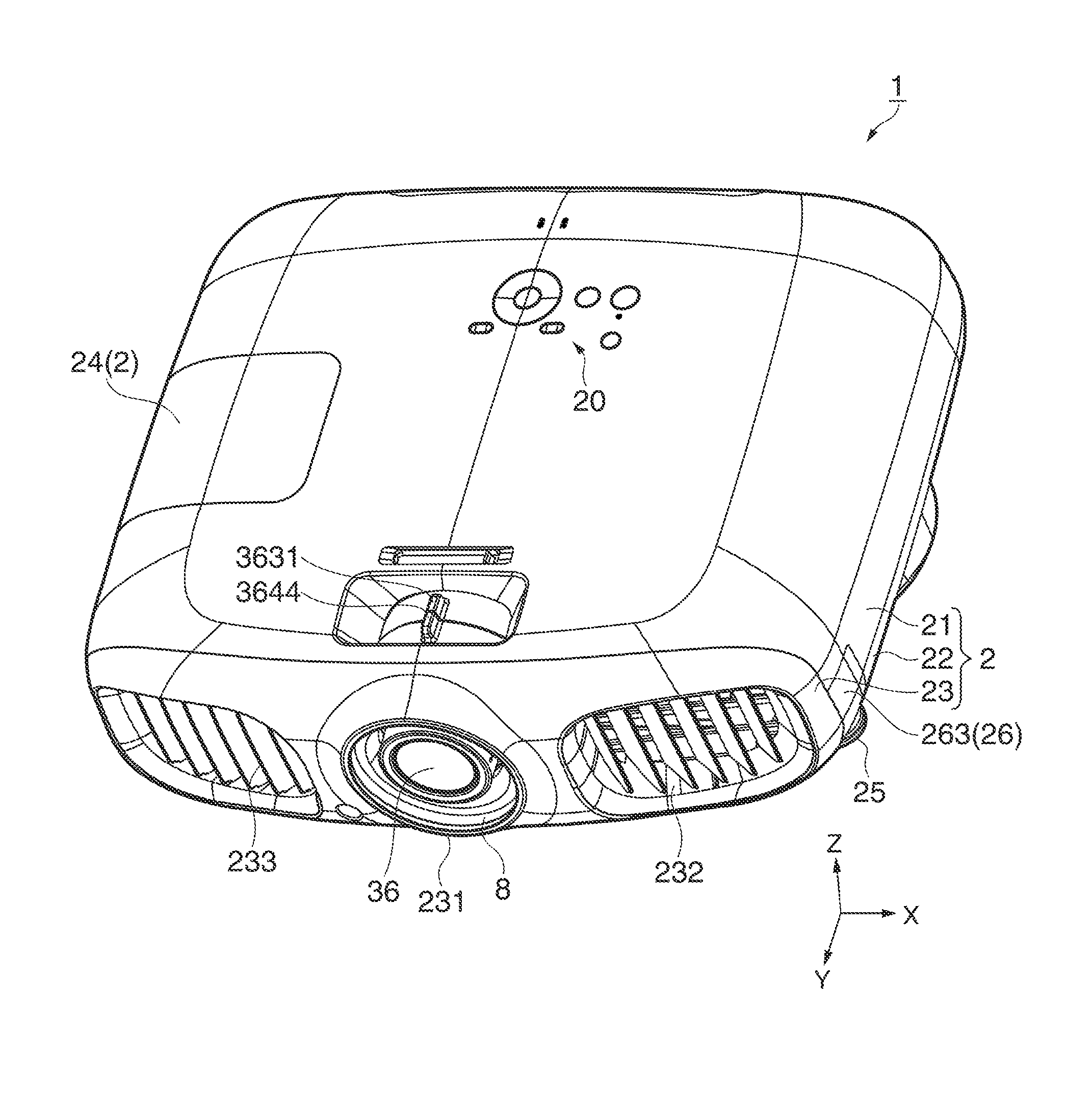
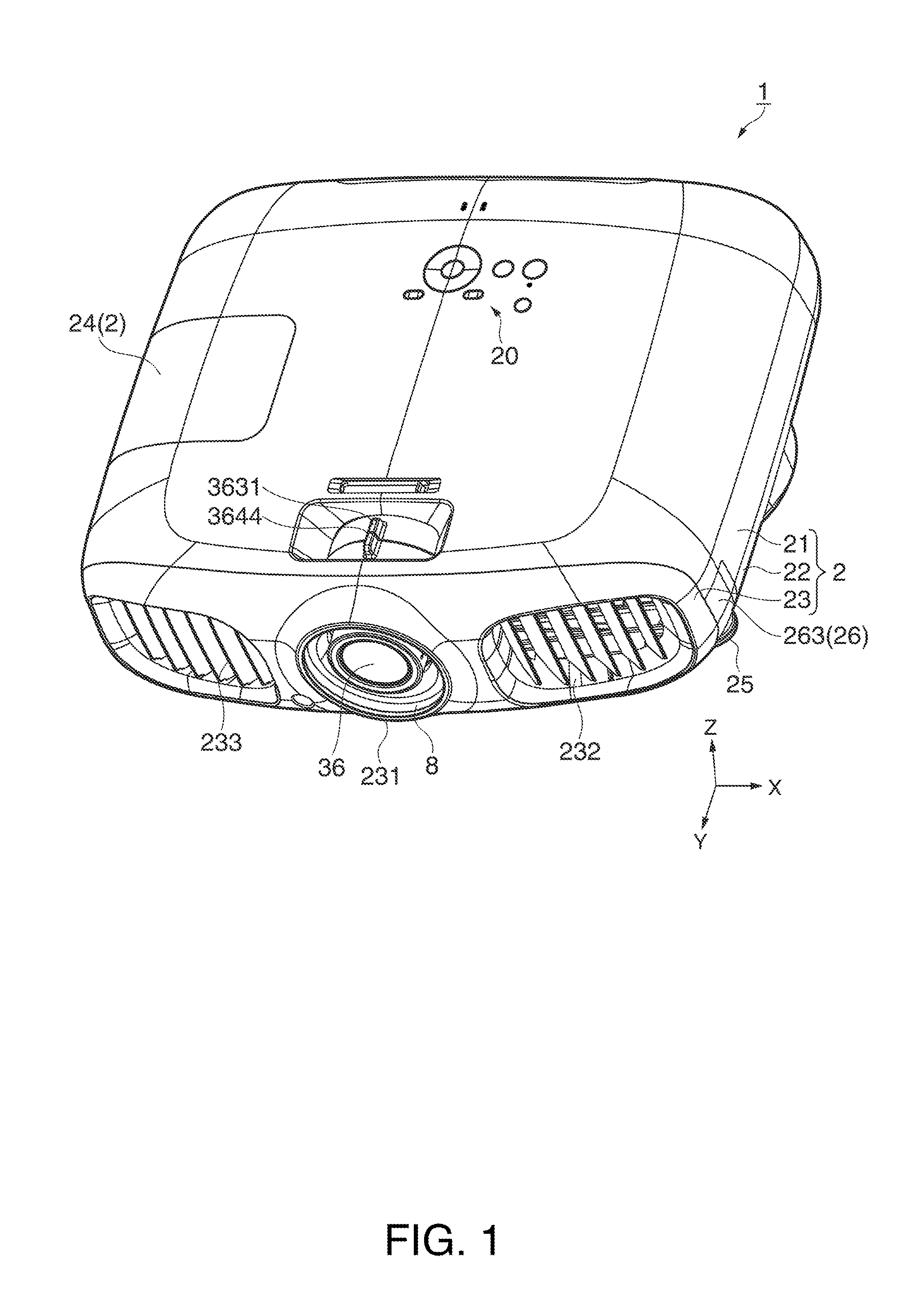
[0011]According to this configuration, the inlet port and the outlet port are formed in the external housing on the side where light is projected from the projection lens. In other words, the projector introduces air for cooling the light modulation device and the second controller from the side of the image to be projected and discharges the air toward the image. Accordingly, the projector can securely cool the light modulation device and the second controller without closure of the inlet port and the outlet port even in such an installation environment where parts and the like are disposed in the vicinity of the side of the projector different from the image side. Moreover, the air discharged from the outlet port does not reach an observer observing the projected image in the vicinity of the side of the projector different from the image side. Thus, the observer is not made uncomfortable by the discharged air during image projection.
[0012]Accordingly, the projector can achieve both reduction of deterioration of the light modulation device and the second controller, and increase in the degree of freedom for the way of installation of the projector and the position of the observer observing the image.Application Example 3
[0020]According to this configuration, the second controller is constituted by the wireless device capable of providing wireless communication. Thus, the wireless device can communicate with the outside by wireless in a stable condition while efficiently cooled by the air flowing along the second channel. Moreover, the wireless device is disposed in such a condition that its receiver or transmitter faces to the side of light projection from the projection lens. In this arrangement, the receiver or transmitter of the wireless device is disposed opposed to the projected image, that is, the projection surface such as a screen. Accordingly, the wireless device can securely communicate with an external wireless device when this external wireless device is positioned in the vicinity of the screen for communicating with the wireless device, that is, installed in such a condition that obstacles to the wireless communication can be decreased under the use environment of the projector.

Problems solved by technology

According to the technology disclosed in JP-A-2010-74671, however, the components of the liquid crystal projector such as the liquid crystal panel may be subject to thermal deterioration by expected generation of heat from the receiver, because the cooling capacity of the cooling mechanism provided within the liquid crystal projector for reducing heat generated from the light source is not sufficient to cool the receiver together with the light source (this problem is not touched upon in the specification of JP-A-2010-74671).
For overcoming this problem, a unit for cooling the receiver may be added to the interior of the projector, in which case, however, the size of the projector increases.
In addition, such a structure which efficiently cools the components (structure for supplying air to a cooling target with high efficiency by a preferable air amount and at a preferable flow speed) for size reduction is difficult to be equipped.
Moreover, the air discharged from the outlet port does not reach an observer observing the projected image in the vicinity of the side of the projector different from the image side.
Thus, heat generated from the light source is not easily conducted to the second controller, in which condition more efficient cooling for the second controller can be achieved.

Method used


Image

  • Projector
  • Projector
  • Projector

Examples


modified example

[0126]This embodiment can be modified in the following manners.

[0127]According to this embodiment, the wireless device4 is positioned above the first introduction port 101. However, the positions of the wireless device 4 and the first introduction port 101 may be switched in the up-down direction such that the wireless device 4 is positioned below the first introduction port 101.

[0128]In the case of the structure which locates the wireless device 4 below the first introduction port 101, the second introduction ports 201 may be formed in the bottom of the wireless device storage portion 202, in which arrangement the inlet port 232 communicating with the second introduction ports 201 may be formed in the bottom or other positions of the external housing 2.

[0129]According to this embodiment, the first introduction port 101 and the second introduction ports 201 are disposed side by side in the up-down direction. However, the first introduction port 101 and the second introduction ports ...


PUM


Abstract

A projector includes a wireless device performing a predetermined function, an external housing which accommodates a light modulation device, a first controller, and the wireless device, an intake fan which introduces air outside the external housing into the external housing through an inlet port, an exhaust fan which discharges the air introduced into the external housing through the inlet port to the outside through an outlet port, a first channel which guides the air introduced through the inlet port toward the light modulation device by the drive of the intake fan, and a second channel which guides the air introduced into the external housing toward the exhaust fan via the wireless device by the drive of the exhaust fan.

Description

BACKGROUND[0001]1. Technical Field[0002]The present invention relates to a projector.[0003]2. Related Art[0004]A projector is known which modulates light emitted from a light source according to image information and enlarges and projects the modulated light onto a projection surface such as a screen. The light source included in this type of projector is constituted by a discharge-type lamp such as an extra-high pressure mercury lamp, for example. The projector having this structure is provided with a cooling mechanism including a cooling fan and others so as to avoid generation of heat from components of the projector during lighting of the light source. Moreover, with the development of wireless transmission technology in recent years, a system containing a receiver which receives an image signal transmitted from an external device by wireless has been proposed (for example, see JP-A-2010-74671).[0005]An image display system disclosed in JP-A-2010-74671 includes an image signal o...

Claims


Application Information

Patent Timeline
Patent Type & Authority Patents(United States)
IPC IPC(8): G03B21/16
CPCG03B21/145G03B21/006G03B21/16G03B21/2026G03B21/2033
Inventor SHIRAKURA, KIYOMASA
Owner SEIKO EPSON CORP
Why Eureka
Try Eureka