Exoscope

a technology of exoscope and microscope, which is applied in the field of exoscope, can solve the problems of large space occupation, large volume of apparatus, and large space occupation of surgical microscope, and achieve the effect of stable and robust structur

Active Publication Date: 2014-04-22
KARL STORZ GMBH & CO KG
View PDF9 Cites 36 Cited by
  • Summary
  • Abstract
  • Description
  • Claims
  • Application Information

AI Technical Summary

Benefits of technology

[0019]It is therefore the object of the present invention to further develop an exoscope for the purpose of providing a stable, robust structure and ensuring that an object field can be sufficiently illuminated and observed at distances that extend to the meter range.

Problems solved by technology

The apparatus is very unwieldy in structure and occupies a relatively large amount of space in the area above the object field.
This surgical microscope is also very unwieldy in structure, in particular because it comprises a very wide bracket in order to be able to bring the surgical microscope into numerous different positions relative to the object field.
This requires a relatively lengthy practice phase, but then leads to the surgeon being able to perform minimally invasive procedures in a relatively relaxed position, whether standing or seated.
If the distances between the lens and the object field are relatively large, such as more than the previously mentioned 20 cm, the object field can no longer be sufficiently observed and the lens no longer conveys an optimal image.
These rib retractors are mechanically very stable tools, which are relatively unwieldy and accordingly demand a sufficiently large space for manipulation over the object field.

Method used


Image

  • Exoscope
  • Exoscope
  • Exoscope

Examples


second embodiment

[0114]an exoscope, shown in FIGS. 9 through 12, is designated in its entirety with reference number 80. Here too the exoscope 80 comprises a lens 82 and an illumination 84. Here as well, an elongated cylindrical shaft 86, closed and hollow in this embodiment, is foreseen with a head member 90 mounted on its distal end 88. A first illuminating unit 92 as well as a second illuminating unit 94 is also positioned in the head member 90. Here, again, the radiating direction 93 of the illuminating unit 92 as well as the radiating direction 95 of the illuminating unit 94 is directed in such a way that it runs at an angle of approximately 90 degrees to the longitudinal axis 87 of the shaft 86.

[0115]The lens 82 is inserted from the proximal end into a guide tube 100 of the shaft 86 and is firmly connected with the head 90, as can be seen in FIG. 12.

[0116]The lens 82 too is once again configured as a 90 degree lens, that is, its viewing direction 83, as can be seen in particular from FIG. 9, r...

third embodiment

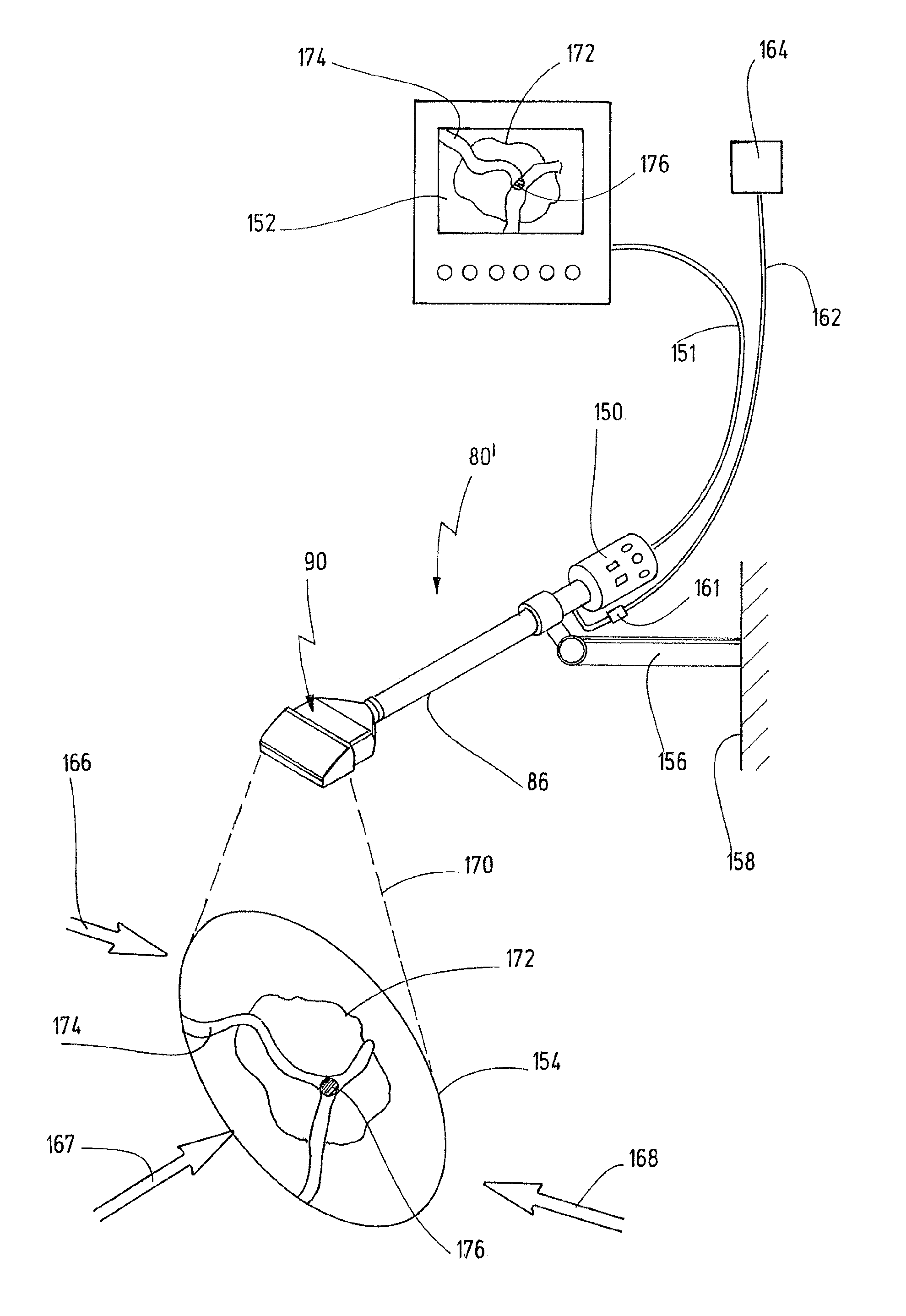
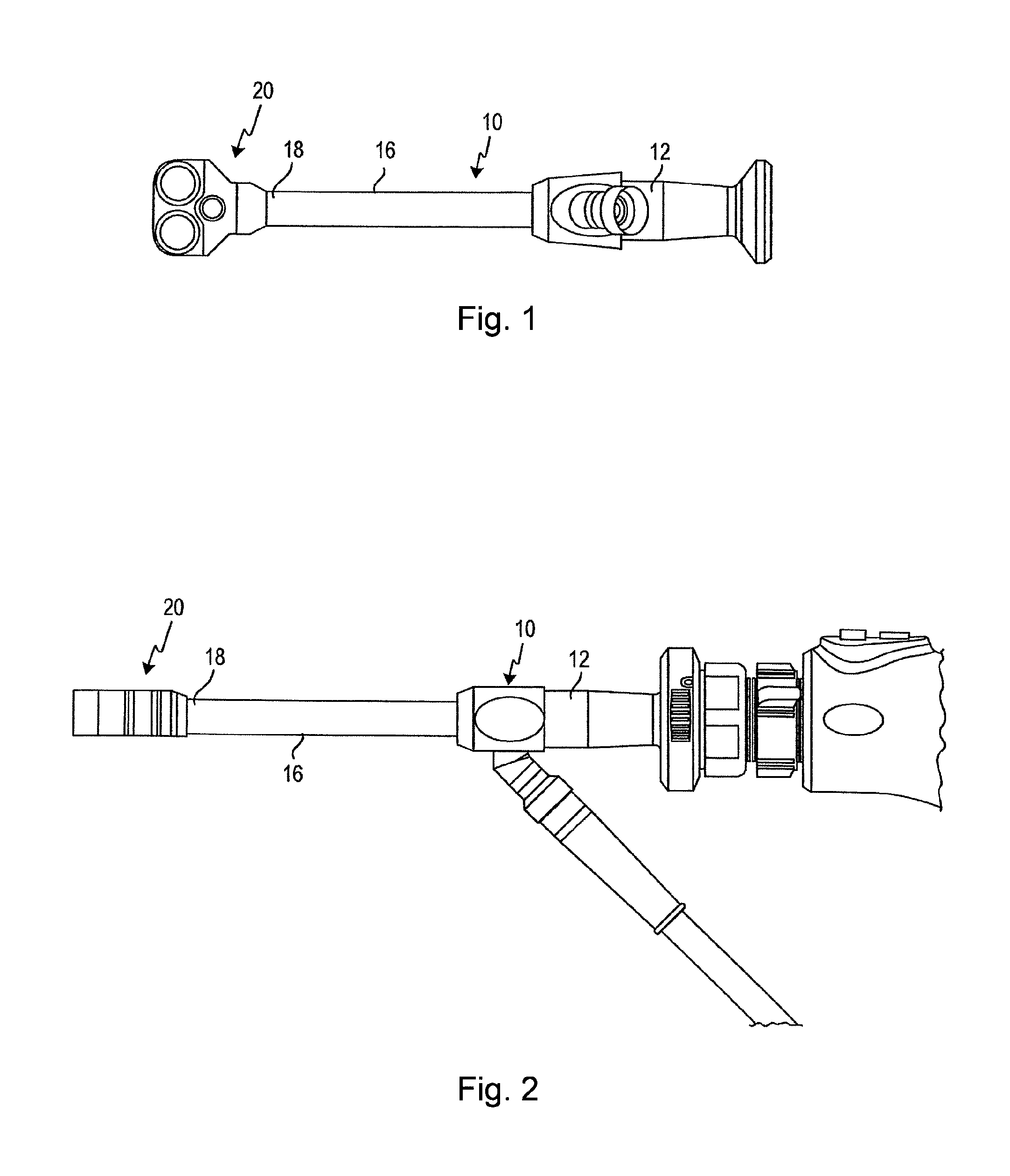
[0121]Illustrated in FIGS. 14 and 15 is an exoscope, which is designated in its entirety with the reference number 110. The exoscope 110 also comprises a lens 112 that is enclosed in a shat 114. The viewing direction 113 of the lens 112 here follows the direction of the longitudinal axis 115 of the shaft, and is thus a lens 112 with a zero degree viewing angle. Here too, once again, positioned on the proximal end of the shaft 114 is a head member 116 in which two illuminating units 118 and 120 are enclosed whose radiating directions 119 and 121 are likewise aligned in the direction of the longitudinal axis 115. FIG. 15 shows how the exoscope 110 is mounted on a stationary site 142 by means of a bracket 134. This site is usually the operating table or a special tripod.

[0122]For this purpose the bracket 134 can comprises a multiply jointed arm 136 that is connected with the shaft 144 by a clamp 138. A screw 140 allows a separable connection between the bracket 134 and endoscope 110, w...

fifth embodiment

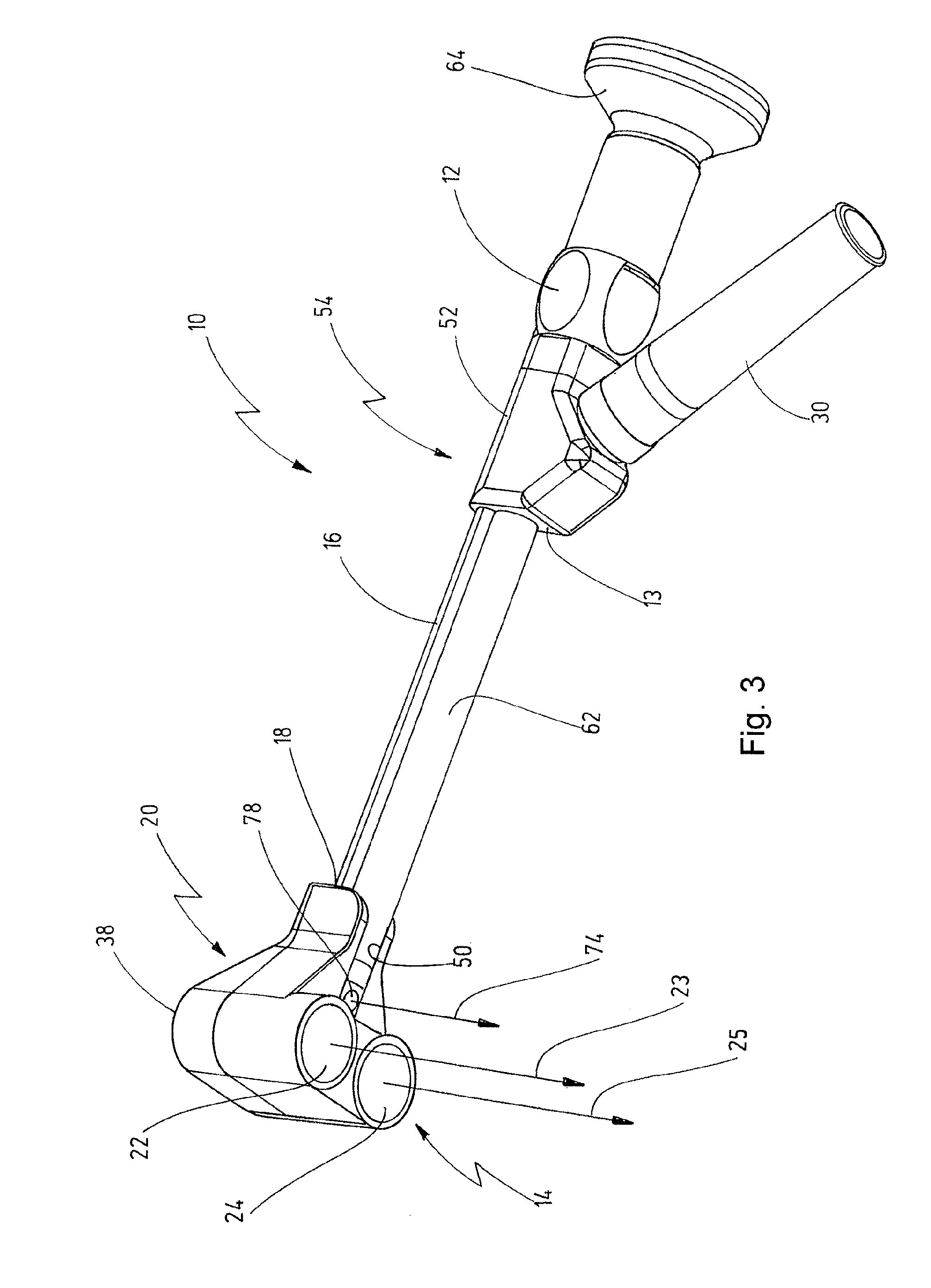
[0126]Illustrated in FIGS. 17 and 18 is an inventive exoscope, which is designated in its entirety with reference number 180.

[0127]Here again the exoscope 180 comprises a base member 184 in which a lens 182 is enclosed. An eyepiece 183 is present at the proximal end.

[0128]The viewing direction 185 of the lens 182 runs at a 90 degree angle to its longitudinal axis.

[0129]The lens 182 is contained in a shaft 186 of the exoscope 180. A head member 190 is provided on the distal end 188 of the shaft 186.

[0130]As can be recognized in particular from the section view in FIG. 18, the distal end of the lens 182 ends in this head member 190.

[0131]A single illumination unit 192 is contained in the head member 190.

[0132]Its radiating direction 193 likewise runs at an angle of approximately 90 degrees to the longitudinal axis 187 of the shaft 186, and this longitudinal axis 187 also extends in the direction of the longitudinal axis of the lens 182.

[0133]Contained in the shaft 186 are light conduc...


PUM


Abstract

An exoscope serves for observing and illuminating an object field on a patient from a position set apart from the patient's body. A lens system serves to observe the object field and an illumination serves to illuminate the object field. A distance between the lens system and the object field can be modified by a bracket. A shaft comprises on its distal end a head member that is widened in comparison to it, so that the illumination reaches into the distal-side head member. Positioned in the head member is at least one radiating illumination unit whose radiant characteristic can be adjusted in such a way that the object field can be illuminated homogeneously at all possible distances from the lens system. Supply lines for the at least one illuminating unit are positioned in the shaft.

Description

CROSS-REFERENCE TO RELATED APPLICATIONS[0001]The present application claims the benefit under 35 U.S.C. §119 (e) of the U.S. Provisional Patent Application Ser. No. 61 / 476,660 filed on Apr. 18, 2011.FIELD OF THE INVENTION[0002]The invention relates to an exoscope for observing and illuminating an object field on a patient from a site outside the patient's body, with a lens system for observing the object field and with an illumination to illuminate the object field, a distance between lens system and object field can be modified by a bracket.BACKGROUND OF THE INVENTION[0003]Apparatuses for illuminating an object field in an OR and also apparatuses for observing the object field are known in a variety of configurations.[0004]From WO 2004 / 100815 A2, a surgical field illumination apparatus is known that comprises a large-surface illuminating unit and an integrated optic observation device. Here the observation device in particular can be a surgical microscope. This makes it possible to...

Claims


Application Information

Patent Timeline
Patent Type & Authority Patents(United States)
IPC IPC(8): A61B1/06
CPCA61B19/5212A61B19/5202A61B90/361A61B90/30
Inventor BERCI, GEORGEKOEHLER, BENEDIKTLEIDOLT, CHRISTOPHLEDERER, FRANKWEIGER, ULRICHDAHMEN, JANLEI, FANG
Owner KARL STORZ GMBH & CO KG
Why Eureka
Try Eureka