Motor vehicle radar system, and method for determining speeds and distances of objects

a technology for motor vehicles and radars, applied in the direction of reradiation, measurement devices, instruments, etc., to achieve the effect of high updating rate, low required measuring time, and high updating ra

Active Publication Date: 2014-04-22
VALEO SCHALTER & SENSOREN
View PDF33 Cites 9 Cited by
  • Summary
  • Abstract
  • Description
  • Claims
  • Application Information

AI Technical Summary

Benefits of technology

[0022]Using these two frequency ramps allows this embodiment to form a hypothesis by determining the intersections of resulting straight lines with little required measuring time for a part-area. This, too, contributes to a desirably high updating rate.
[0023]A further embodiment is distinguished by the fact that at least four different frequency ramps, of which two are in each case located in one of two different measuring cycle

Problems solved by technology

The requirements for a high update rate and for accuracy of the measurem

Method used


Image

  • Motor vehicle radar system, and method for determining speeds and distances of objects
  • Motor vehicle radar system, and method for determining speeds and distances of objects
  • Motor vehicle radar system, and method for determining speeds and distances of objects

Examples


Embodiment Construction

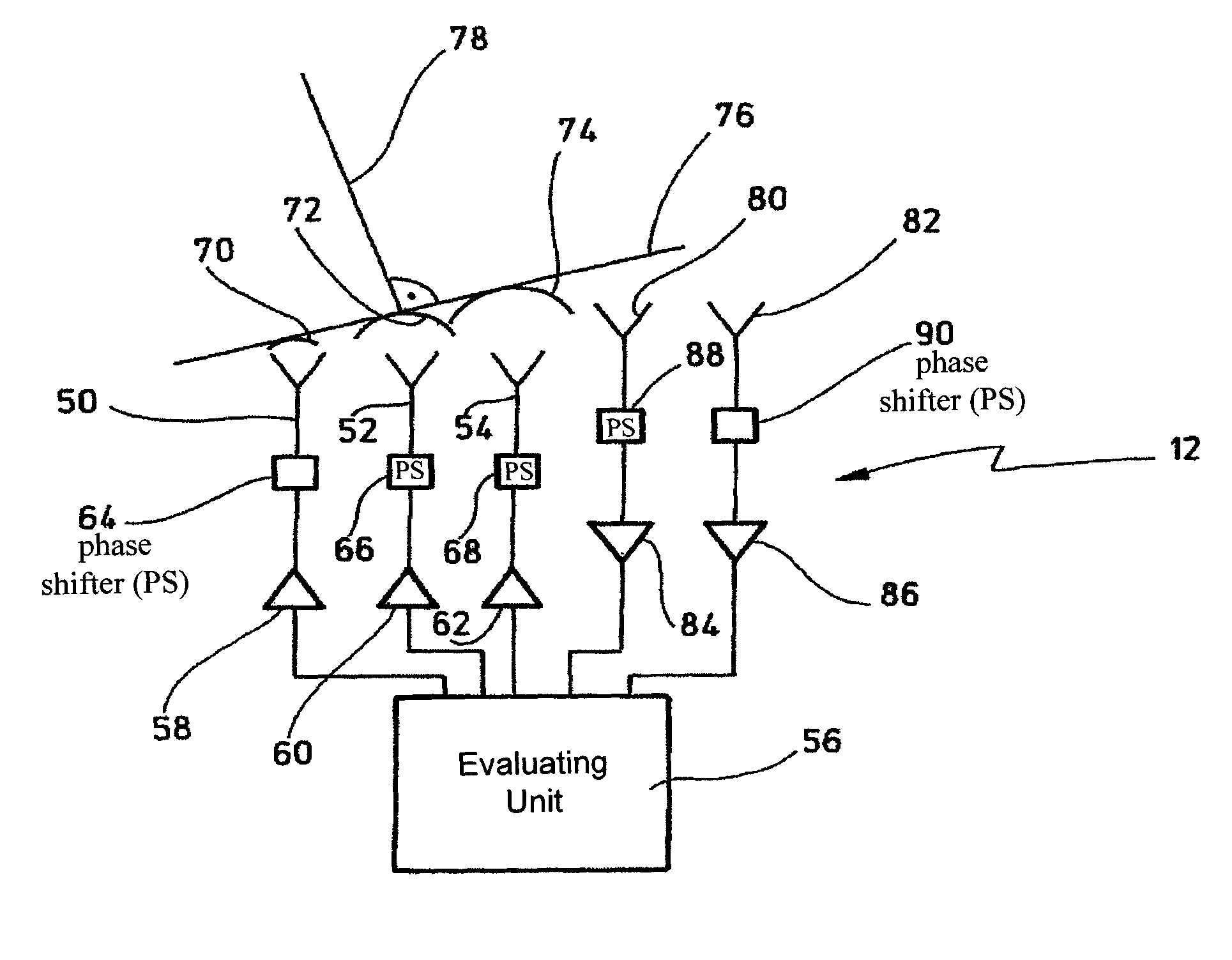
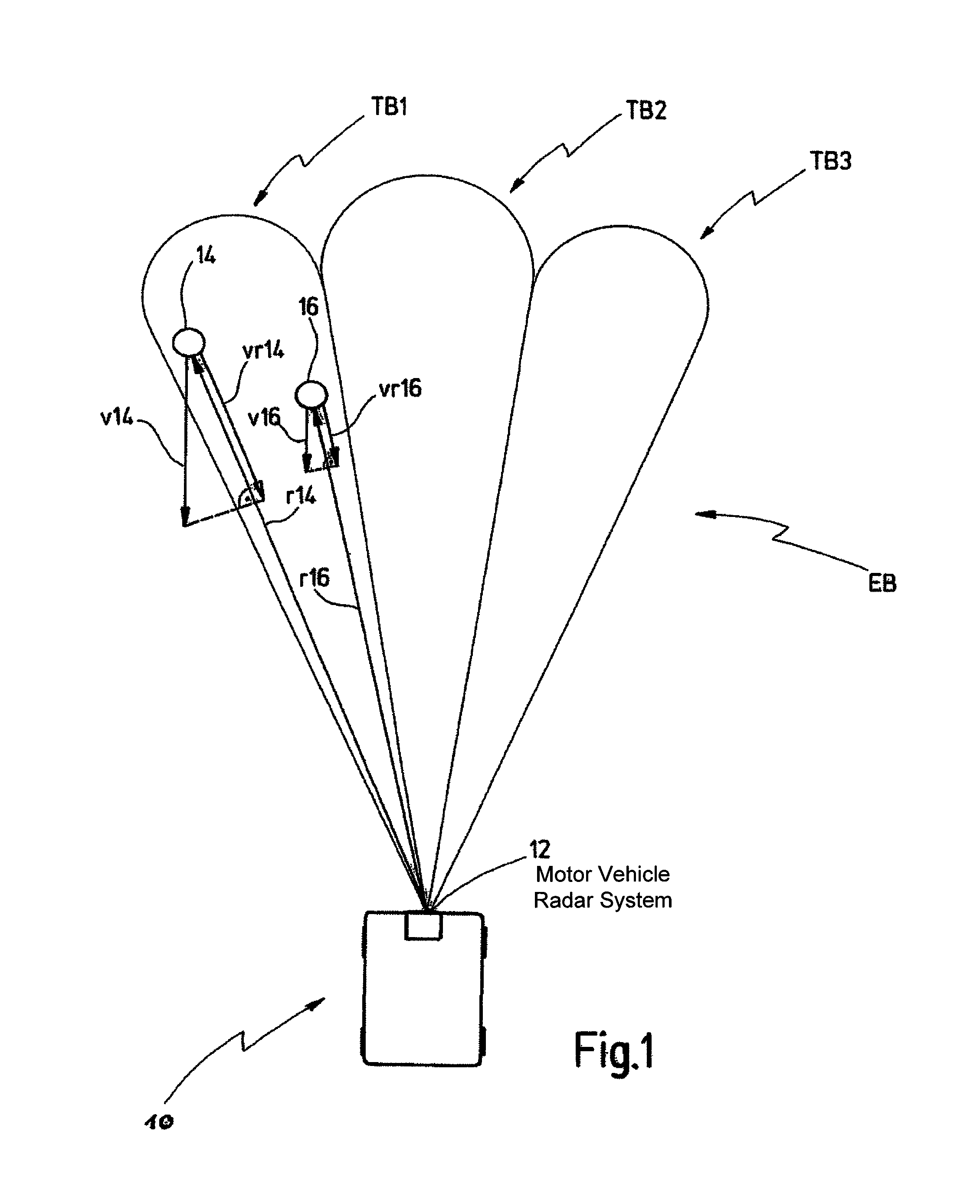
[0040]FIG. 1 shows a motor vehicle 10 with a motor vehicle radar system 12 which determines radial components vr14, vr16 of speeds v14, v16 and distances r14, r16 of objects 14, 16 relative to the motor vehicle 10. In this context, the radar system 12 is arranged for using a coverage area EB divided into N=3 part-areas TB1, TB2, TB. Other values N greater than or equal to 2 are also possible. Each part-area TB1, TB2, TB3 is implemented as overlay of a transmitting lobe and of an angular receiving area.

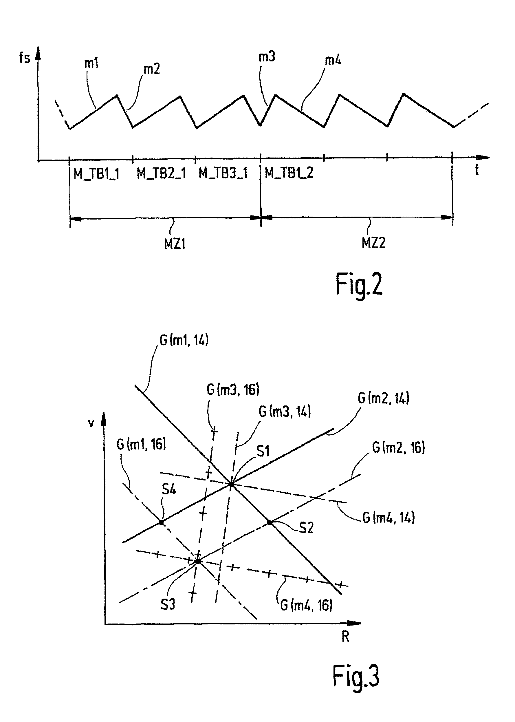
[0041]The overlays point in various spatial directions and, in a first embodiment, are sequentially activated in a measuring cycle so that the radar system 12 examines the coverage area EB section by section for reflecting objects 14, 16. Each examination in one of the part-areas will also be called individual measurement in the text which follows. In the same way in which the part-areas TB1, TB2, TB3 together produce the coverage area EB, the duration of a measuring cycle is obtained ...


PUM


Abstract

Presented is a method for determining speeds (vr14, vr16) and distances (r14, r16) of objects (14, 16) relative to a radar system (12) of a motor vehicle (10), wherein a coverage area (EB) of the radar system (12) is divided into at least two part-areas (TB1, TB2, TB3), the coverage area (EB) is examined for reflecting objects (14, 16) in successive measuring cycles (MZ1, MZ2; MZi, MZi+1), wherein radar signals received in a measuring cycle (MZ1, MZ2; MZi, MZi+1) are processed separated in accordance with part-areas (TB1, TB2, TB3) and processed signals are assembled to form a total result differentiated in accordance with spatial directions. The method is characterized in that from signals received in a first measuring cycle (MZ1; MZi), hypotheses for the distance (r14, r16) and speed (vr14, vr16) of reflecting objects (14, 16) are formed and the hypotheses are validated in dependence on signals received in at least one further measuring cycle (MZ2; MZi+2). Furthermore, a radar system (12) is presented which carries out such a method.

Description

FIELD OF THE INVENTION[0001]The invention relates to a method for determining speeds and distances of objects relative to a radar system of a motor vehicle, wherein a coverage area of the radar system is divided into at least two part-areas, the coverage area is examined for reflecting objects in successive measuring cycles, wherein radar signals received in a measuring cycle are processed separated in accordance with part-areas and processed signals are assembled to form a total result differentiated in accordance with spatial directions. The invention also relates to a radar system which is arranged for carrying out the method.BACKGROUND OF THE INVENTION[0002]Such a method and such a radar system is in each case known from DE 696 12 252 T2.[0003]In road motor vehicles, radar systems are used for monitoring the vehicle environment, considering applications such as parking aid, monitoring of dead angle, track-change assistance, door-opening assistance, pre-crash sensing for triggeri...

Claims


Application Information

Patent Timeline
IPC IPC(8): G01S13/28G01S13/00G01S13/93G01S13/931
CPCG01S13/931G01S13/343G01S13/584G01S2013/9325
Inventor LUEBBERT, URSHABERLAND, UDO
Owner VALEO SCHALTER & SENSOREN
Why Eureka
Try Eureka