Interleaved circuit of flexure for disk drive

a technology of interleaved circuit and disk drive, which is applied in the field of interleaved circuit of flexure, can solve the problems of limited design flexibility of flexure with conductors, inability to reduce the distance between the branch conductors unlimitedly, and the resist formed between each adjacent branch conductor cannot be reduced unlimitedly, so as to prevent the effect of widening and reducing the impedan

Active Publication Date: 2014-04-22
NHK SPRING CO LTD
View PDF13 Cites 8 Cited by
  • Summary
  • Abstract
  • Description
  • Claims
  • Application Information

AI Technical Summary

Benefits of technology

[0014]Accordingly, the object of the present invention is to provide an interleaved circuit of a flexure for a disk drive, capable of being reduced in impedance and prevented from becoming wide.
[0016]According to this arrangement, the interleaved circuit can be reduced in impedance and prevented from becoming wide.

Problems solved by technology

In this arrangement, the distance between the branch conductors cannot be reduced unlimitedly, due to the use of resists for the formation of the branch conductors by etching or plating.
In this case, the width of a resist formed between each two adjacent branch conductors cannot be reduced unlimitedly.
If all the branch conductors are located on the same plane of the insulating layer to reduce impedance, as described above, the interleaved circuit is so wide that the design flexibility of a flexure with conductors is limited.

Method used


Image

  • Interleaved circuit of flexure for disk drive
  • Interleaved circuit of flexure for disk drive
  • Interleaved circuit of flexure for disk drive

Examples


first embodiment

[0035]A first embodiment will now be described with reference to FIGS. 1 to 5.

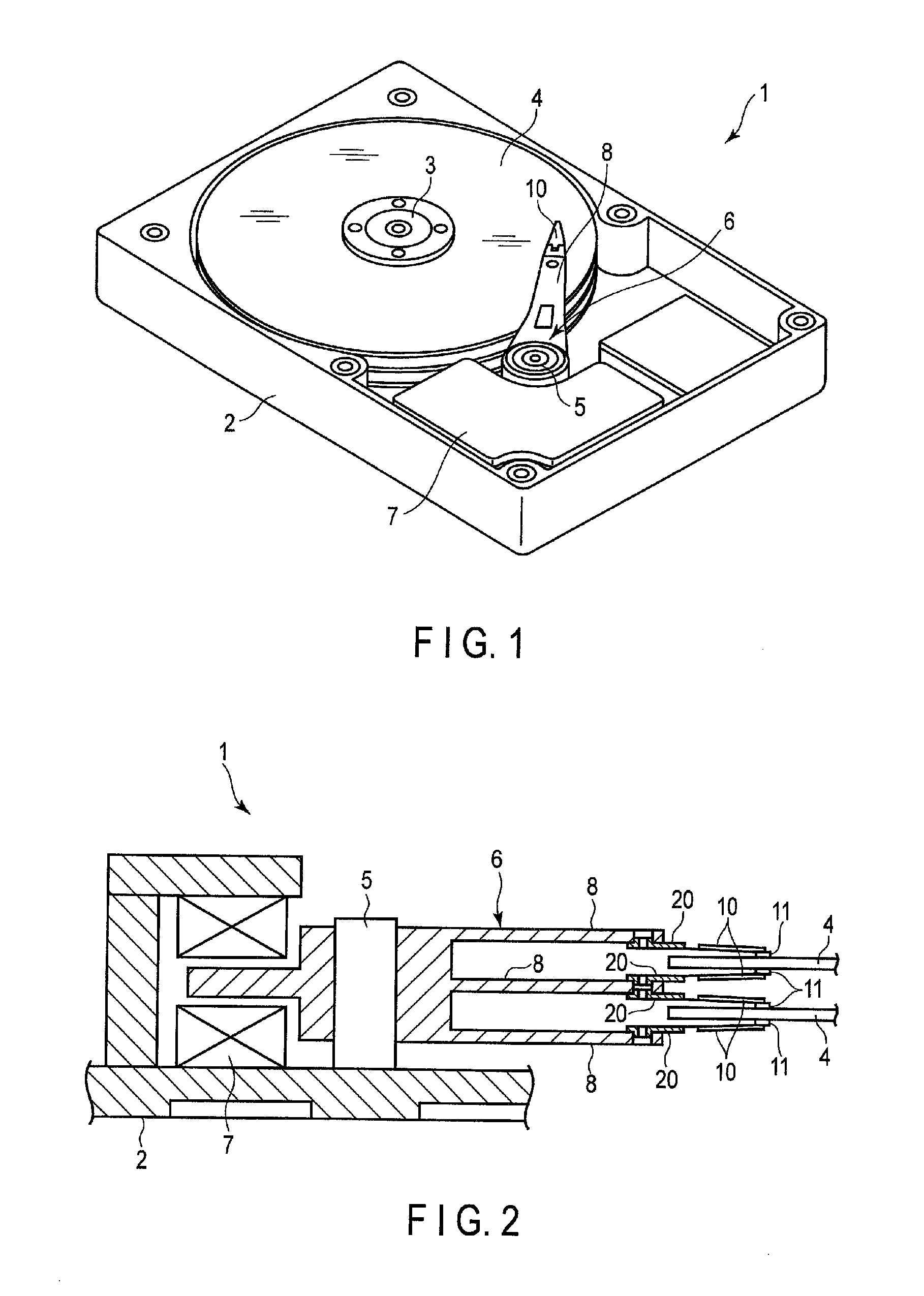
[0036]A hard disk drive (hereinafter referred to as the disk drive) 1 shown in FIG. 1 comprises a case 2, spindle 3, magnetic disks 4, pivot 5, carriage 6, and positioning motor 7. The magnetic disks 4 are rotatable about the spindle 3, while the carriage 6 is turnable about the pivot 5. The positioning motor 7 serves to turn the carriage 6. The case 2 is sealed by a lid (not shown).

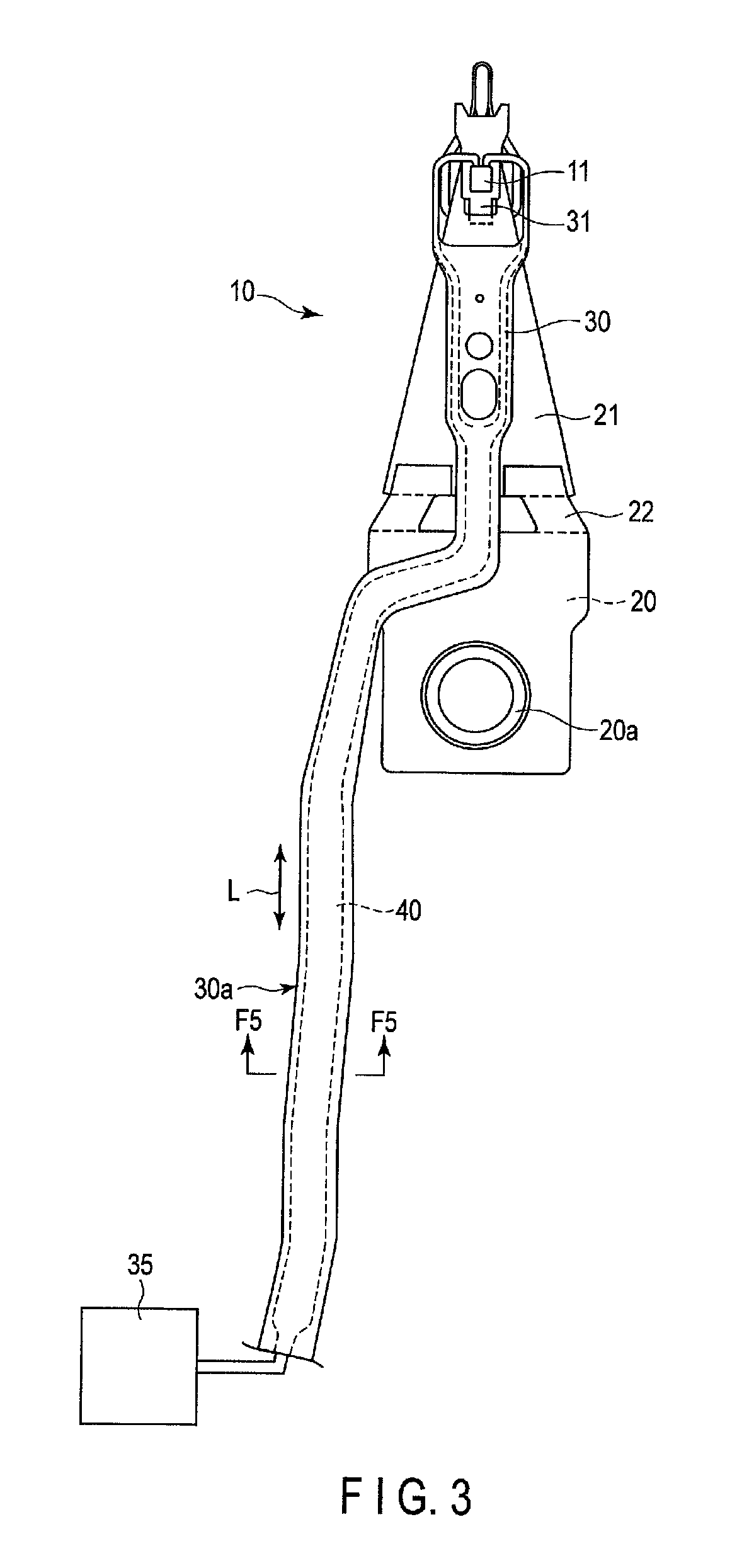
[0037]FIG. 2 is a sectional view schematically showing a part of the disk drive 1. As shown in FIG. 2, the carriage 6 comprises a plurality (e.g., three) of actuator arms 8. A suspension 10 is mounted on the distal end portion of each arm 8. A slider 11, which constitutes a magnetic head, is disposed on the distal end of the suspension 10.

[0038]Each magnetic disk 4 is rotated about the spindle 3 at high speed, an air bearing is formed between the disk and the slider 11. If the carriage 6 is turned by the positioning motor 7, th...

second embodiment

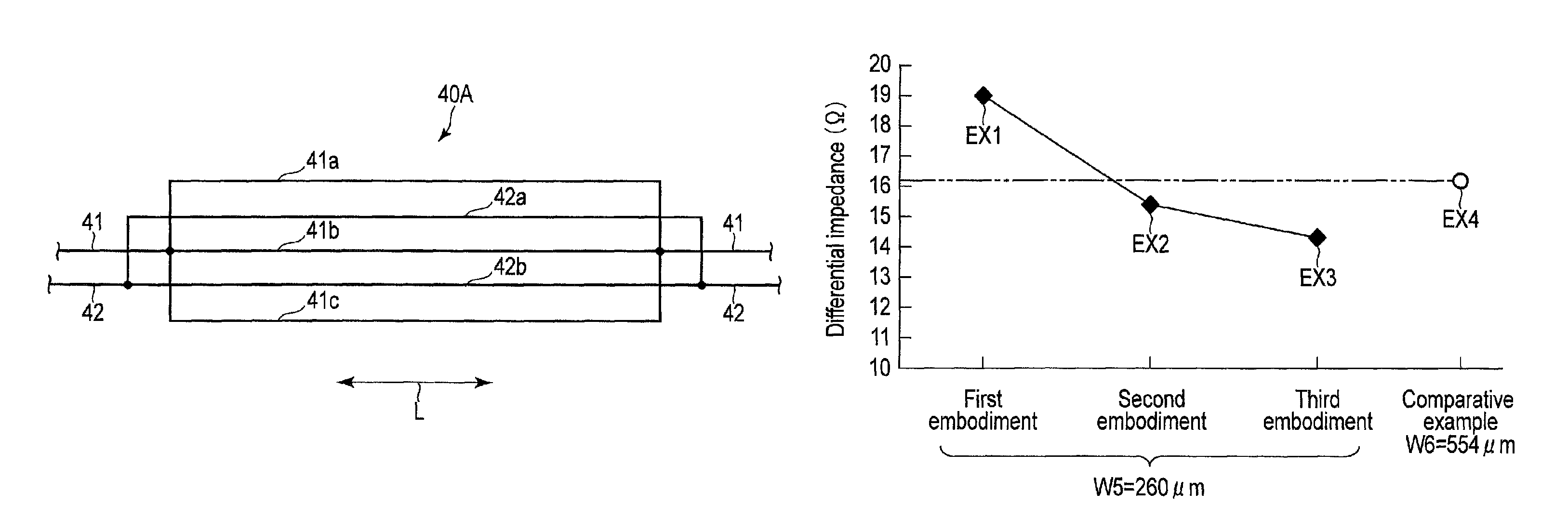
[0056]FIG. 6 shows an interleaved circuit 40B according to a The cross-section of each of second branch conductors 42a′ and 42b′ of this interleaved circuit 40B is in the shape of an inverted trapezoid. Specifically, the second branch conductors 42a and 42b′ shown in FIG. 6 each comprise a first flat surface portion 71 in contact with a first cover resin layer 61, second flat surface portion 72 opposite to the first flat surface portion 71, and opposite side surfaces 73 and 74. The opposite side surfaces 73 and 74 are inclined so that the distance between them increases with distance from the first flat surface portion 71 toward the second flat surface portion 72. Thus, width W3 of the first flat surface portion 71 is smaller than width W4 of the second flat surface portion 72. Widths W3 and W4 are, for example, 45 μm and 55 μm, respectively. The cross-sections of first branch conductors 41a to 41c are rectangular, and width W1 is, for example, 30 μm.

[0057]According to the interlea...

fourth embodiment

[0063]FIG. 10 shows an interleaved circuit 40D according to a This interleaved circuit 40D comprises recesses 90 in a second surface 51b of an insulating layer 51. These recesses 90 are formed individually between first branch conductors 41a, 41b and 41c. A part of a first cover resin layer 61 fills each recess 90. Second branch conductors 42a and 42b are located in positions individually corresponding to the recesses 90 with the first cover resin layer 61 between them.

[0064]Thus, in the interleaved circuit 40D of the fourth embodiment, the second branch conductors 42a and 42b are located in the recesses 90, individually. Therefore, the first branch conductors 41a to 41c are flush with the second branch conductors 42a and 42b. Since the other configurations of the interleaved circuit 40D are the same as those of the interleaved circuit 40A of the first embodiment (FIG. 5), common numbers are used to designate common parts of the first and fourth embodiments, and a repeated descript...


PUM

PropertyMeasurementUnit
distance G0aaaaaaaaaa
thicknessaaaaaaaaaa
thicknessaaaaaaaaaa

Abstract

An interleaved circuit has first branch conductors branching from a first conductor, second branch conductors branching from a second conductor, a metal base having an opening, an insulating layer formed on the metal base, an electrically insulating first cover resin layer, and an electrically insulating second cover resin layer. The first branch conductors are formed on the insulating layer. The first branch conductors are covered by the first cover resin layer. The second branch conductors are formed on the first cover resin layer. The second branch conductors are individually located between the first branch conductors. The second branch conductors are covered by the second cover resin layer.

Description

CROSS-REFERENCE TO RELATED APPLICATIONS[0001]This application is based upon and claims the benefit of priority from prior Japanese Patent Application No. 2012-000531, filed Jan. 5, 2012, the entire contents of which are incorporated herein by reference.BACKGROUND OF THE INVENTION[0002]1. Field of the Invention[0003]This invention relates to an interleaved circuit of a flexure used in a disk drive for an information processing apparatus, such as a personal computer.[0004]2. Description of the Related Art[0005]A hard disk drive (HDD) is used in an information processing apparatus, such as a personal computer. The HDD comprises a magnetic disk rotatable about a spindle, a carriage turnable about a pivot, etc. A disk drive suspension is disposed on an arm of the carriage.[0006]The disk drive suspension comprises a baseplate, load beam, etc. A flexure is disposed on the load beam. A slider is mounted on a gimbal portion formed near the distal end of the flexure. The slider is provided wi...

Claims


Application Information

Patent Timeline
Patent Type & Authority Patents(United States)
IPC IPC(8): G11B5/48
CPCG11B5/486G11B5/484
Inventor ARAI, HAJIME
Owner NHK SPRING CO LTD
Why Eureka
Try Eureka