Method and system for enhanced scanner user interface

a scanner and user interface technology, applied in the field of vehicle diagnostic methods and systems, can solve problems such as time-consuming and confusing

Active Publication Date: 2014-04-22
SNAP ON INC
View PDF8 Cites 386 Cited by
  • Summary
  • Abstract
  • Description
  • Claims
  • Application Information

AI Technical Summary

Problems solved by technology

It is not only time cons

Method used


Image

  • Method and system for enhanced scanner user interface
  • Method and system for enhanced scanner user interface
  • Method and system for enhanced scanner user interface

Examples


Embodiment Construction

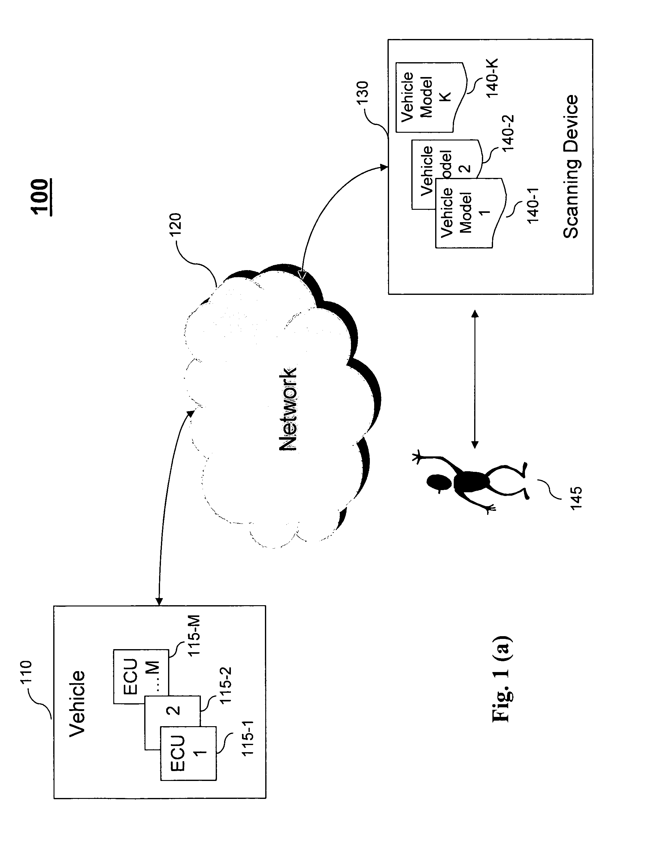
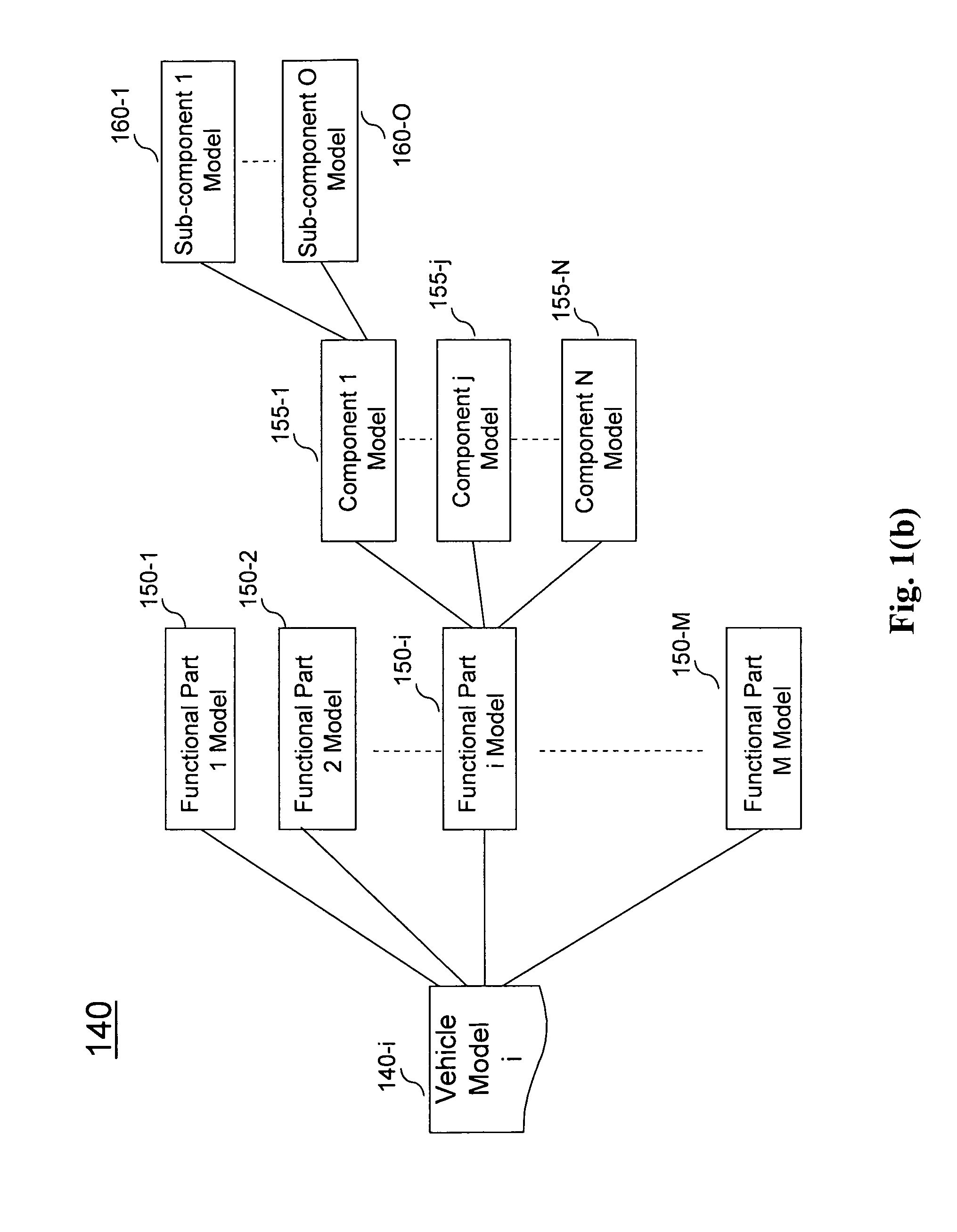
[0017]FIG. 1 depicts an exemplary diagram of a system 100 in which a scanning device 130 having at least one vehicle model stored therein interacts with a vehicle 110 to obtain and present information, according to an embodiment of the present teaching. In the exemplary system 100, the scanning device 130 stores K vehicle models 140-1, 140-2, . . . , 140-k, corresponding to different types of vehicles. In some embodiments, the scanning device 130 is an external device, including a computer, a laptop, a hand held device, or any small devices such as a Palm Pilot and a cellular phone. In some embodiments, the scanning device 130 is internal to the vehicle 110. In some embodiments, the scanning device 130 may be an external device to vehicle 110 but an internal device to another vehicle.

[0018]The scanning device 130 may be deployed with network communication capabilities enabling the scanning device 130 to communicate with the vehicle 110 via a network 120. The network 120 may correspo...


PUM


Abstract

A method and system for presenting vehicle information. A functional part of a vehicle is selected to be examined and information related to the selected function part is received. A vehicle model corresponding to the vehicle is retrieved. Based on the selected functional part and the vehicle model, a mode of operation is determined and used in presenting the vehicle model and the information so that a portion of the model corresponding to the functional part is visible and the information is presented with respect to the visible functional part of the presented model.

Description

TECHNICAL FIELD[0001]The disclosure relates generally to automotive systems. More specifically, the disclosure relates to method and system for vehicle diagnosis.BACKGROUND ART[0002]In current vehicle diagnosis, a user often uses a scanner to read out information related to a vehicle system via one or more electronic control units (ECUs) in the vehicle. The scanner then presents such information to the user in one or more lists. Frequently, the user has to sort out as to which parameter in a list shows what type of information and which value relates to which function or component of the vehicle. It is not only time consuming but also confusing.BRIEF DESCRIPTION OF THE DRAWINGS[0003]The invention claimed and / or described herein is further described in terms of exemplary embodiments. These exemplary embodiments are described in detail with reference to the drawings. These embodiments are non-limiting exemplary embodiments, in which like reference numerals represent similar structures...

Claims


Application Information

Patent Timeline
IPC IPC(8): G06F3/00
CPCG07C5/0825G07C5/0816
Inventor HOEVENAAR, ROBERT
Owner SNAP ON INC
Why Eureka
Try Eureka