Planetary gear type multi-stage transmission

Active Publication Date: 2014-04-29
ZF FRIEDRICHSHAFEN AG
View PDF9 Cites 78 Cited by
  • Summary
  • Abstract
  • Description
  • Claims
  • Application Information

AI Technical Summary

Benefits of technology

[0005]Based on the prior art described above, the problem addressed by the present invention is to provide a planetary gear multi-stage transmission which is distinguished by a compact construction, particularly in the axial direction.

Problems solved by technology

The latter is only possible, however, if the shift element concerned is to be transferred only from an engaged state into a disengaged state with an upshift along the gear sequence.

Method used


Image

  • Planetary gear type multi-stage transmission
  • Planetary gear type multi-stage transmission
  • Planetary gear type multi-stage transmission

Examples


Embodiment Construction

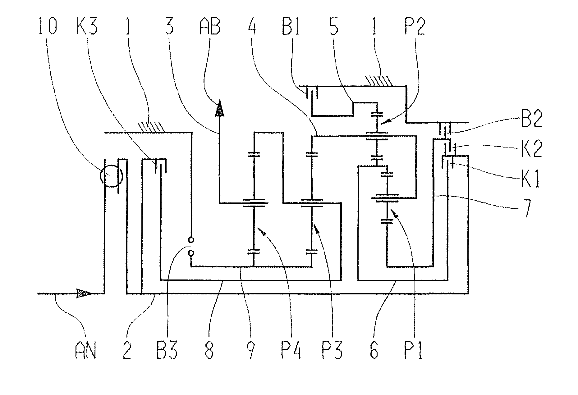
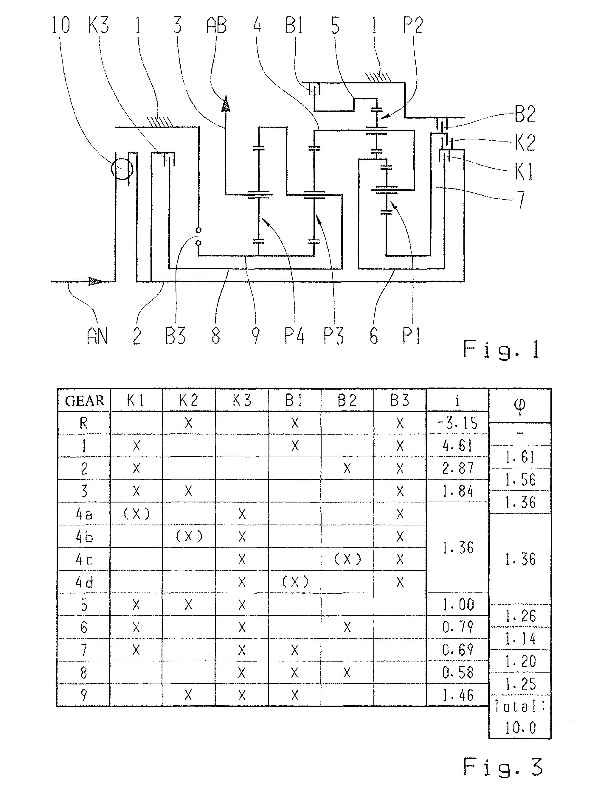
[0024]FIG. 1 shows a schematic representation of a multi-stage transmission according to a preferred embodiment of the invention. This multi-stage transmission has a housing 1, which accommodates four planetary gear sets P1 to P4, several shafts 2 to 9, and shift elements in the form of clutches K1 to K3 and brakes B1 to B3. According to an actuation of the clutches K1 to K3 and the brakes B1 to B3, different transmission ratios can be implemented between a drive shaft 2 connected to a input side AN of the transmission and an output shaft 3 that runs transverse to the drive shaft 2 and which forms the output side AB of the multi-stage transmission.

[0025]The four planetary gear sets P1 to P4 are each presently designed as minus planetary gear sets, wherein the first planetary gear set P1 and the second planetary gear set P2 form a shiftable input side gear set, while the third planetary gear set P3 and the fourth planetary gear set P4 define a main gear set of the multi-stage transmi...


PUM


Abstract

A motor vehicle multi-stage planetary transmission which has a housing that accommodates four planetary gear sets (P1, P2, P3, P4), shafts (2-9), three clutches (K1, K2, K3) and three brakes (B1, B2, B3) whose selective actuation implements various transmission ratios between drive and output shafts. The carriers of gear sets (P1, P2) are connected by shaft (4), the ring gear of gear set (P2) can be fixed to the housing, via shaft (5), by actuating brake (B1). A ring gear of gear set (P1) and a sun gear of gear set (P2) are coupled by shaft (6) which can be connected, via clutch (K1), to the drive shaft. A sun gear of gear set (P1) can be fixed, via brake (B2), to the housing and can be coupled, by clutch (K2), to drive shaft. The first and second clutches (K1, K2) are startup elements which initiate startup procedures.

Description

[0001]This application claims priority from German patent application serial no. 10 2012 207 018.4 filed Apr. 27, 2012.FIELD OF THE INVENTION[0002]The invention relates to a multi-stage transmission in planetary design, particularly an automatic transmission of a motor vehicle, having a housing, which accommodates four planetary gear sets and several shafts, and having clutches and brakes, by means of the targeted actuation of which various transmission ratios can be represented between a drive shaft and an output shaft running coaxially to the drive shaft, wherein a carrier of a first planetary gear set is connected by means of a third shaft to a carrier of a second planetary gear set, the ring gear of which can be fixed to the housing by means of a fourth shaft by actuating of a first brake, wherein further a ring gear of the first planetary gear set and a sun gear of the second planetary gear set are coupled by a fifth shaft, which can be connected via a first clutch to the drive...

Claims


Application Information

Patent Timeline
Patent Type & Authority Patents(United States)
IPC IPC(8): F16H3/44
CPCF16H3/62F16H3/66F16H2003/442F16H2061/0046F16H2200/0065F16H2200/2012F16H2200/2046
Inventor SCHERER, HERIBERTBAUKNECHT, GERTZIEMER, PETER
Owner ZF FRIEDRICHSHAFEN AG
Why Eureka
Try Eureka