Oscillation circuit

a technology of oscillator and circuit, applied in the direction of oscillator generator, generator stabilization, pulse automatic control, etc., can solve the problem that the ability to drive the load cannot be adjusted

Inactive Publication Date: 2014-04-29
MITSUMI ELECTRIC CO LTD
View PDF5 Cites 1 Cited by
  • Summary
  • Abstract
  • Description
  • Claims
  • Application Information

AI Technical Summary

Benefits of technology

[0009]Accordingly, embodiments of the present invention may provide a novel and useful oscillation circuit, which can change a capability of driving a load, solving one or more of the problems discussed above.

Problems solved by technology

However, if the impedance of the load outwardly connected to the oscillation circuit is changed, a capability of driving the load cannot be adjusted so as to be suitable for the changed impedance of the load with the conventional technique.

Method used


Image

  • Oscillation circuit
  • Oscillation circuit
  • Oscillation circuit

Examples


first embodiment

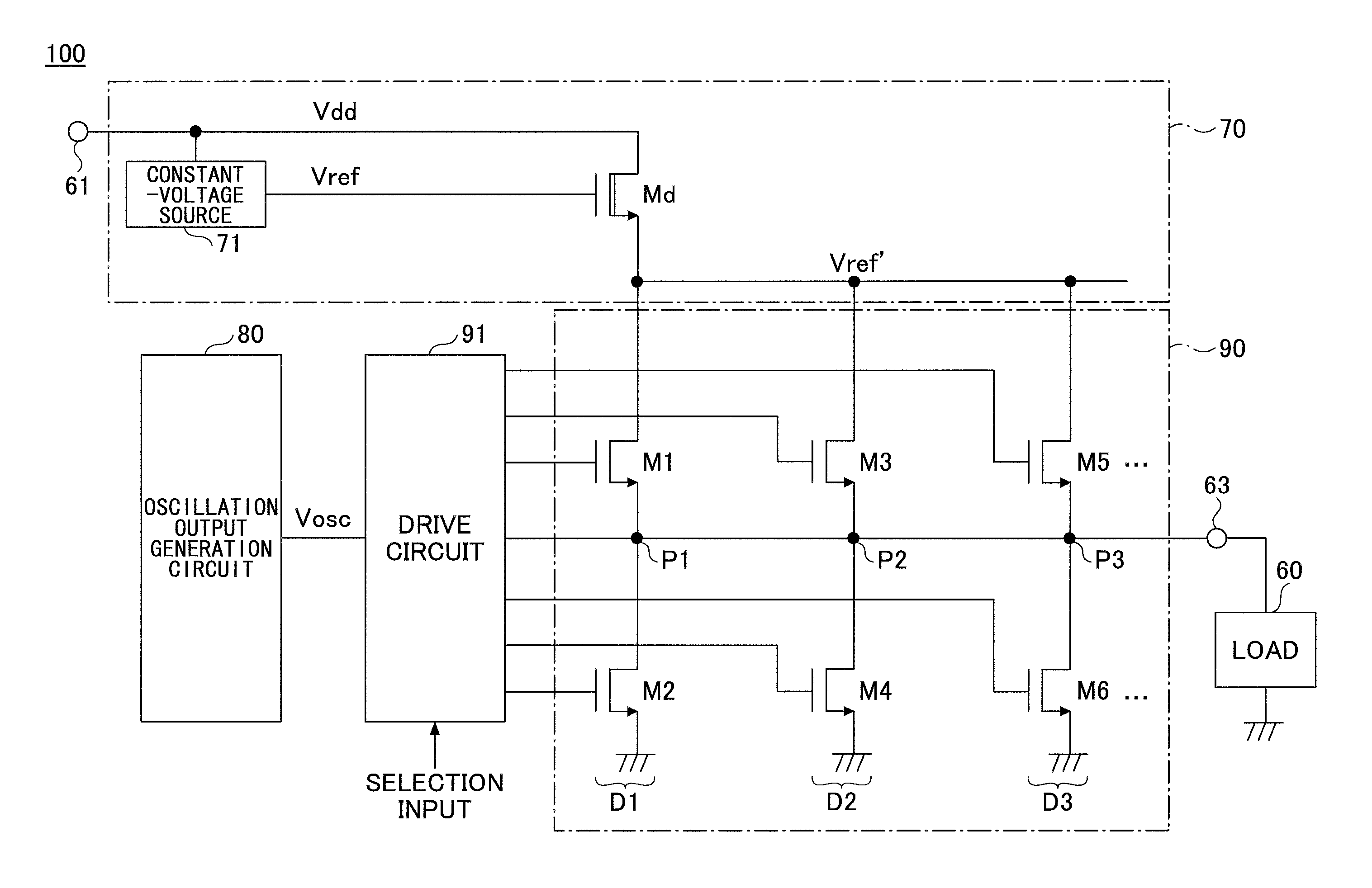
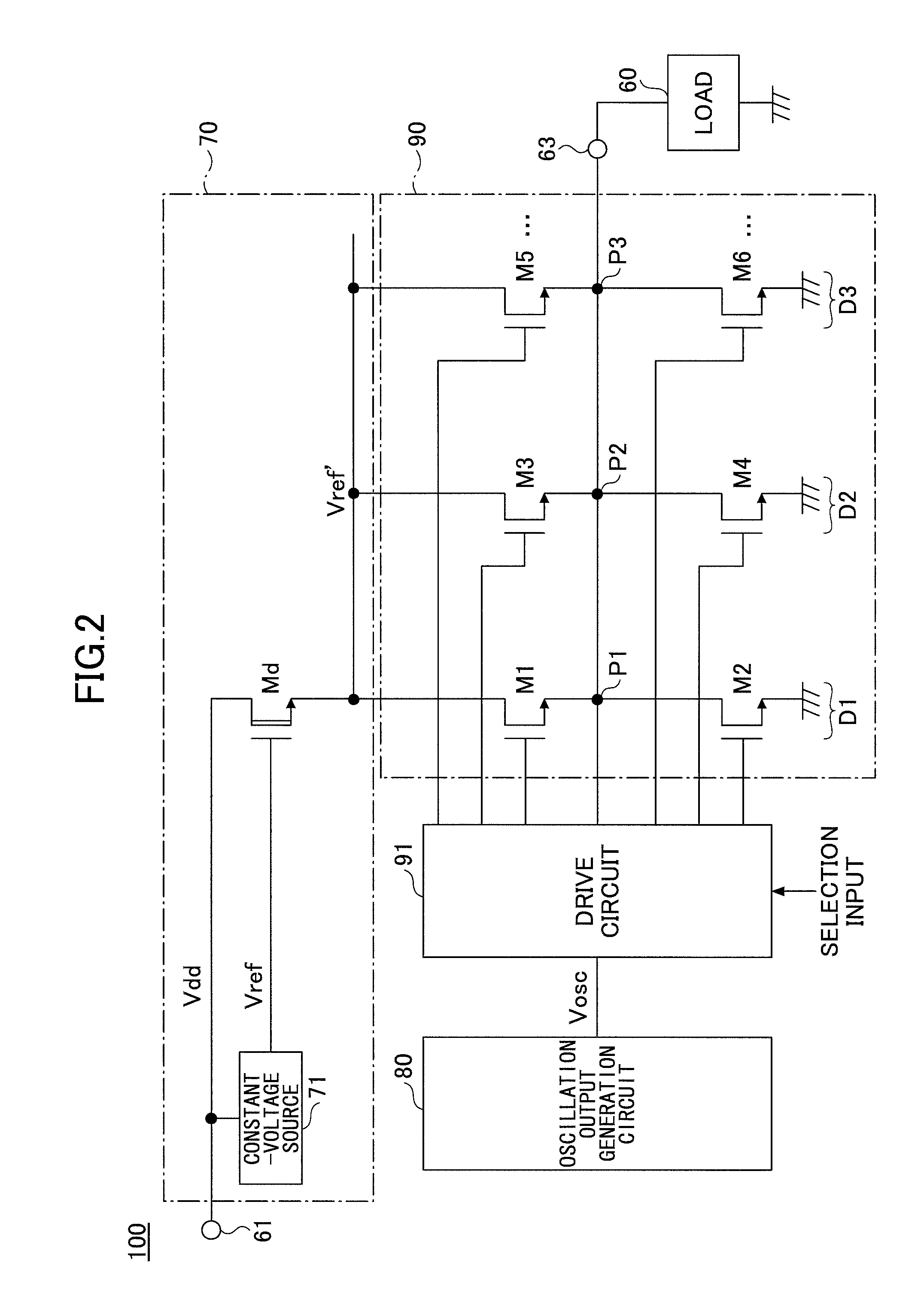
[0040]FIG. 2 is a block chart of an oscillation circuit 100 of a first embodiment of the present invention. The oscillation circuit 100 includes a constant-voltage generation circuit 70, an oscillation output generation circuit 80, an output circuit 90 and a drive circuit 91.

[0041]The constant-voltage generation circuit 70 is satisfactory if it can generate a constant voltage Vref′. FIG. 2 illustrates the constant-voltage generation circuit 70 including a constant-voltage source 71 and a transistor Md as a depression-type n-channel MOSFET. The constant-voltage source 71 generates a predetermined reference voltage Vref based on a supply voltage Vdd input from a supply voltage input terminal 61. The constant-voltage source 71 may be a resistance voltage dividing circuit or the like. The constant-voltage source 71 is preferably a regulator in order to stabilize the reference voltage Vref. The supply voltage Vdd is supplied to the drain of the transistor Md, and the reference voltage Vr...

second embodiment

[0050]The second embodiment is described next as a more specific example than that on the first embodiment illustrated in FIG. 2. FIG. 3 is a block chart of a temperature-compensated crystal oscillator (TCXO) 200 of the second embodiment of the present invention. The TCXO 200 includes an integrated circuit (IC). The TCXO 200 is an oscillation circuit including a temperature compensation circuit 20, a voltage-controlled crystal oscillator (VCXO) 30 in which a crystal unit 35 of an AT cut as a resonator, and a memory 40. The VCXO 30 includes the output stage circuit 36 (to be described in detail).

[0051]The temperature compensation circuit 20 is a function generation circuit for outputting a control voltage Vc of the VCXO 30. The temperature compensation circuit 20 compensates a variation of the oscillating frequency of the crystal unit 35 caused by a change in an ambient temperature T by applying a control voltage Vc generated based on an ambient temperature T, which is detected by a ...


PUM


Abstract

A disclosed oscillation circuit includes a constant-voltage generation circuit, an oscillation generation circuit configured to generate an oscillation output, an output circuit including a plurality of parallelly arranged MOSFET circuits, to which a constant voltage generated by the constant-voltage generation circuit is supplied as a supply voltage, output points of the plurality of MOSFET circuits being mutually connected, and a drive circuit configured to drive a selected MOSFET circuit selected in response to a selection input among the plurality of MOSFET circuits by the oscillation output, wherein an output from an unselected MOSFET circuit among the plurality of MOSFET circuits other than the selected MOSFET circuits has a high impedance.

Description

CROSS-REFERENCE TO RELATED APPLICATIONS[0001]This patent application is based upon and claims the benefit of priority of Japanese Patent Application No. 2011-130441 filed on Jun. 10, 2011, the entire contents of which are incorporated herein by reference.BACKGROUND OF THE INVENTION[0002]1. Field of the Invention[0003]The present invention generally relates to an oscillation circuit including a MOSFET driven by an oscillation output.[0004]2. Description of the Related Art[0005]It is preferable for an oscillation circuit to output an oscillation waveform having a predetermined oscillating frequency f irrespective of existence of a load or a load current. Therefore, an output stage circuit for ensuring a capability of driving the load and relaxing an influence of the load is necessary.[0006]FIG. 1 illustrates an exemplary output stage circuit 50 of a conventional oscillation circuit 50. The output stage circuit includes a CMOS inverter with which an oscillation output from the oscillat...

Claims


Application Information

Patent Timeline
Patent Type & Authority Patents(United States)
IPC IPC(8): H03B1/00H03L5/00
CPCH03B5/04H03B5/368H03L1/023
Inventor NAKAMURA, TAKAYUKISAKAI, MINORU
Owner MITSUMI ELECTRIC CO LTD
Why Eureka
Try Eureka