Scanning optical positioning system with spatially triangulating receivers

a spatial triangulation and optical positioning technology, applied in the field of 3d positioning, can solve the problems of ineffective camera-based motion tracking systems, difficult for these systems to accurately detect the motion of human participants, and difficult for human participants to interact with virtual environments. , to achieve the effect of minimal data generation, little additional latency, and little to no computing bottlenecks

Active Publication Date: 2014-04-29
SMITS GERARD DIRK
View PDF61 Cites 55 Cited by
  • Summary
  • Abstract
  • Description
  • Claims
  • Application Information

AI Technical Summary

Problems solved by technology

However, enabling a human participant to interact with a virtual environment can be very difficult.
However, camera-based motion tracking systems can be ineffective due to frame rate limitations, high data volumes, and the like.
Frame rate limitations can impose various artifacts in the captured images, such as blurring, which makes it difficult for these systems to accurately detect motion of the human participant.
Additionally, the large amount of data associated with capturing multiple images can introduce latencies that may result in undesirable reaction times by the virtual environment to the movement of the human participant.

Method used


Image

  • Scanning optical positioning system with spatially triangulating receivers
  • Scanning optical positioning system with spatially triangulating receivers
  • Scanning optical positioning system with spatially triangulating receivers

Examples


Embodiment Construction

[0015]Various embodiments now will be described more fully hereinafter with reference to the accompanying drawings, which form a part hereof, and which show, by way of illustration, specific embodiments by which the invention may be practiced. The embodiments may, however, be embodied in many different forms and should not be construed as limited to the embodiments set forth herein; rather, these embodiments are provided so that this disclosure will be thorough and complete, and will fully convey the scope of the embodiments to those skilled in the art. Among other things, the various embodiments may be methods, systems, media, or devices. Accordingly, the various embodiments may take the form of an entirely hardware embodiment, an entirely software embodiment, or an embodiment combining software and hardware aspects. The following detailed description is, therefore, not to be taken in a limiting sense.

[0016]Throughout the specification and claims, the following terms take the meani...


PUM


Abstract

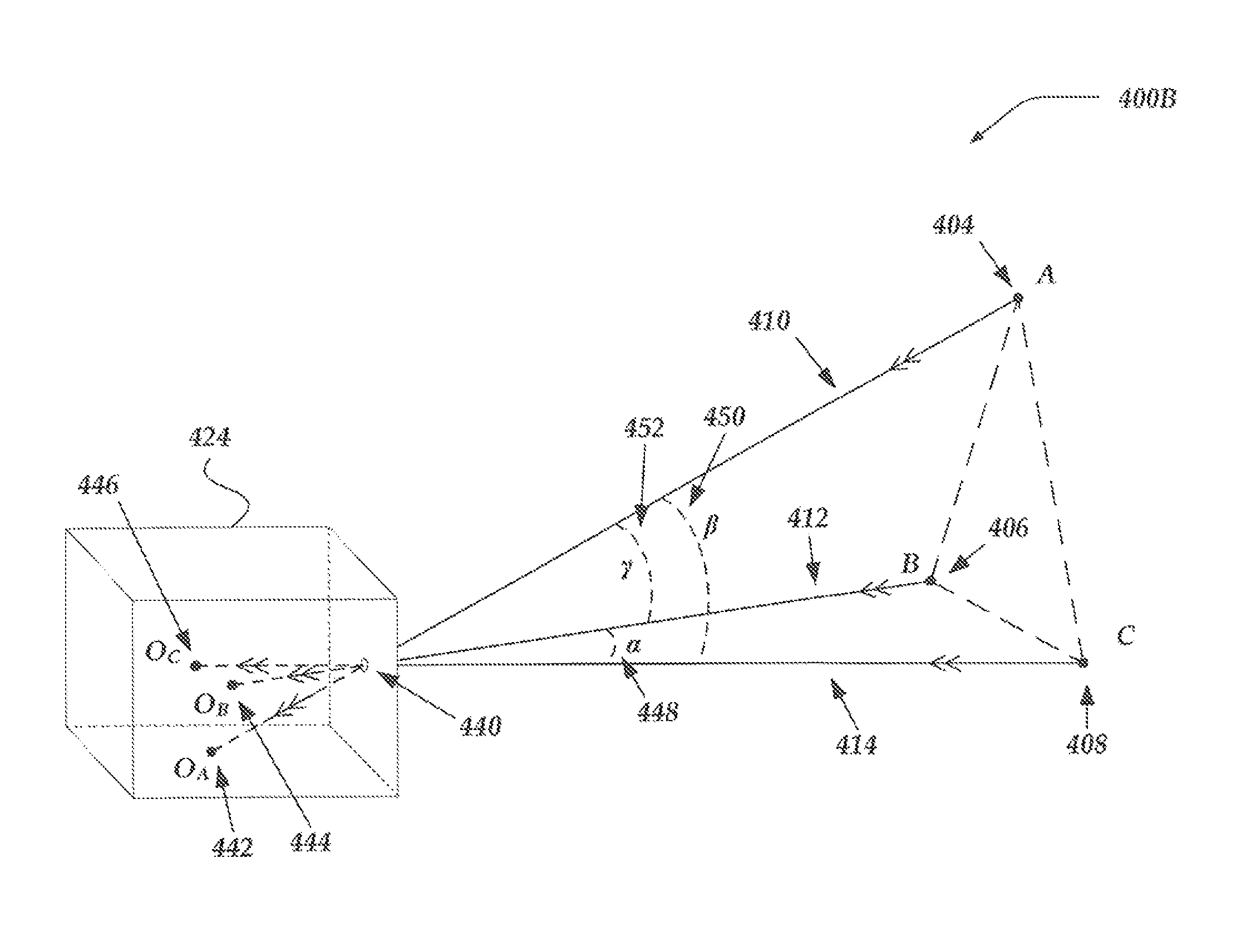
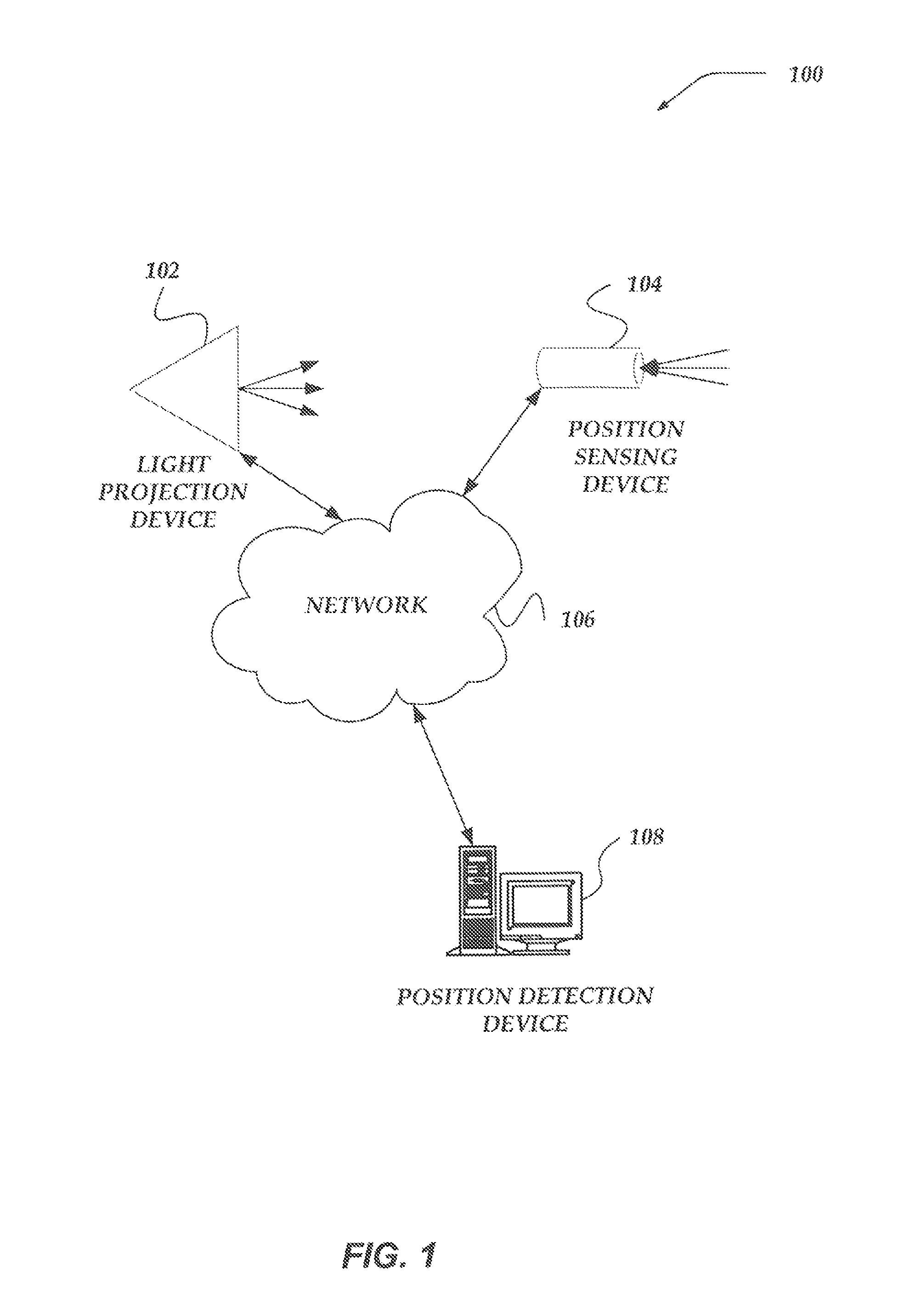
Embodiments are directed towards detecting the three dimensional position of a position sensing device (PSD) utilizing a spot scanned across a remote surface. A trajectory map may be determined for a projection system. The trajectory map may identify a location of the spot at various times during the scan. A PSD may be arranged with a clear view of the remote surface. The PSD may observe at least three spots projected onto the remote surface utilizing three lines of sight that enable moment-in-time linear alignment between the spot and a sensor. Observation angles between each of the lines of sight may be determined. For each observed spot, a transition time may be determined and a location of the observed spot may be determined based on the trajectory map. A position of the PSD may be determined based on determined observed locations and the observation angles of the PSD.

Description

CROSS-REFERENCE TO RELATED APPLICATIONS[0001]This application claims the benefit under 35 U.S.C. §119(e) of U.S. Provisional Patent Application Ser. No. 61 / 744,942 filed on Oct. 4, 2012, which is incorporated herein by reference.TECHNICAL FIELD[0002]The present invention relates generally to 3D positioning, and more particularly, but not exclusively, to employing a pixel trajectory time map of a light projection system to determine the positioning of a remote sensor.BACKGROUND[0003]Today, the utilization of 3D technology and virtual environments can be found in many aspects of life. Virtual environments can be utilized in video games, training simulators, or the like. However, enabling a human participant to interact with a virtual environment can be very difficult. Typically, these systems utilize cameras to capture multiple images to detect motion of the human participant. However, camera-based motion tracking systems can be ineffective due to frame rate limitations, high data vol...

Claims


Application Information

Patent Timeline
Patent Type & Authority Patents(United States)
IPC IPC(8): G01B11/14
CPCG06F3/011G06F3/00G06F3/038G06F3/0346G06F3/0304G01B11/14A63F13/428A63F13/213A63F13/833G06F3/0386
Inventor SMITS, GERARD, DIRK
Owner SMITS GERARD DIRK
Why Eureka
Try Eureka