Solar panel securing system

a solar panel and mounting bracket technology, applied in the field of mounting brackets, can solve the problems of inconsistent installation torque values, installation of bolt arrangements that take considerable time to install, and installation of installation juggles, so as to avoid the cost and weight of a peripheral solar panel frame, fast and easy installation, and easy installation

Active Publication Date: 2014-05-06
A RAYMOND & CO
View PDF129 Cites 31 Cited by
  • Summary
  • Abstract
  • Description
  • Claims
  • Application Information

AI Technical Summary

Benefits of technology

[0004]In accordance with the present invention, a solar panel securing system is provided. In another aspect, a solar photovoltaic panel assembly is mounted to a building roof in a screw-free manner. Another aspect employs a snap-in connection between a member pre-assembled to a solar panel and a roof-mounted fastening bracket. A further aspect adhesively bonds a bracket directly to a glass surface of a solar panel so that the expense and weight of a peripheral solar panel frame are avoided. Pivoting of one side of a solar panel relative to a roof rail is also employed to assist in ease of installation. A method of securing a solar panel is additionally provided.
[0005]The present solar panel securing system is advantageous over traditional devices. For example, in one aspect, a simplified installation motion is employed to engage an auxiliary component, such as a photovoltaic panel assembly, with a mounting hook and / or snap-in tab. In an aspect of the present system, a solar panel is quickly and easily secured to a building roof in a fast manner without requiring the installer to juggle multiple parts such as screws. In another aspect, a fastening bracket is very inexpensive to manufacture. Furthermore, a section of the present system is pre-assembled upon a building roof via an easy to install roof clamp and rail, and another mating section is pre-assembled to the solar panel, prior to assembly of the solar panel assembly to the fastening system. An aspect of the fastening bracket of the present securing system ideally allows for tolerance variations and part expansion. Moreover, an aspect allows for use of a frameless glass solar panel thereby reducing part cost and weight. Additional advantageous and features of the present invention will become apparent in the following description and appended claims, taking in conjunction with the accompanying drawings.

Problems solved by technology

Such conventional methods cause the installer to juggle many loose fasteners while simultaneously holding heavy solar panels and / or roof mounting components, often on a tilted metal roof in unpleasant weather conditions.
Furthermore, such traditional multi-piece screw or bolt arrangements take considerable time to install while also having inconsistent installation torque values, especially in the common situation where many of these solar panel mounting devices are required for each roof.
This leads to roof leaks and is clumsy to install.
Additionally, peripheral frames add undesireable cost and weight to the solar panel assembly, and make them more difficult to raise onto a building roof.

Method used


Image

  • Solar panel securing system
  • Solar panel securing system
  • Solar panel securing system

Examples


Embodiment Construction

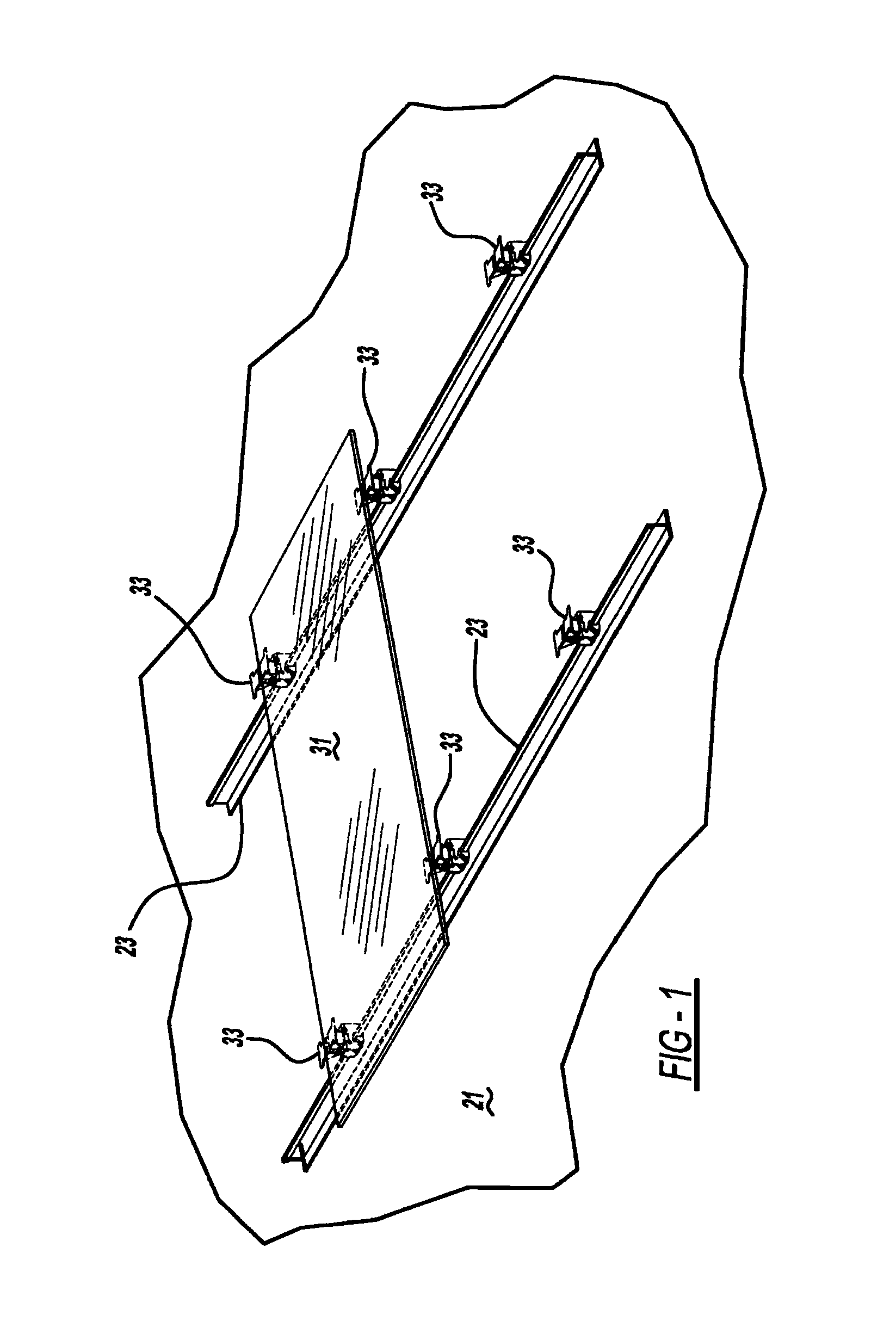
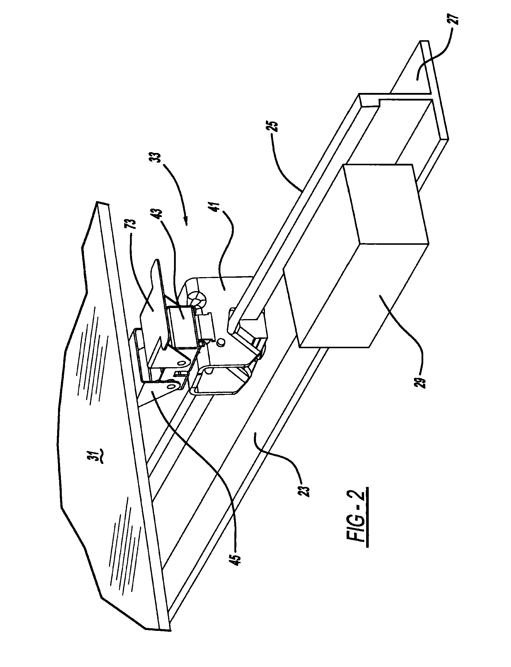
[0013]FIGS. 1-3 illustrate a building having a flat roof 21 upon which is located a pair of parallel rails 23. Each rail 23 has a generally inverted T-shape including an upstanding flange 25 and a flat base 27. Ballast, such as bricks 29, rest upon base 27 to hold each rail 23 upon roof 21 without piercing the roof by screws or the like. Rails 23 are preferably pultruded and resinated, long strand fiberglass which advantageously does not require electrical grounding, avoids corrosion and is light weight. Alternately, the rails can be aluminum, steel or other materials although various advantages will not be realized. Auxiliary roof components, preferably multiple photovoltaic or solar panels 31, are secured to flanges 25 by way of multiple securing systems 33. Each solar panel 31 includes metal and glass sheets with silicon wafers, preferably without peripherally surrounding mounting frames.

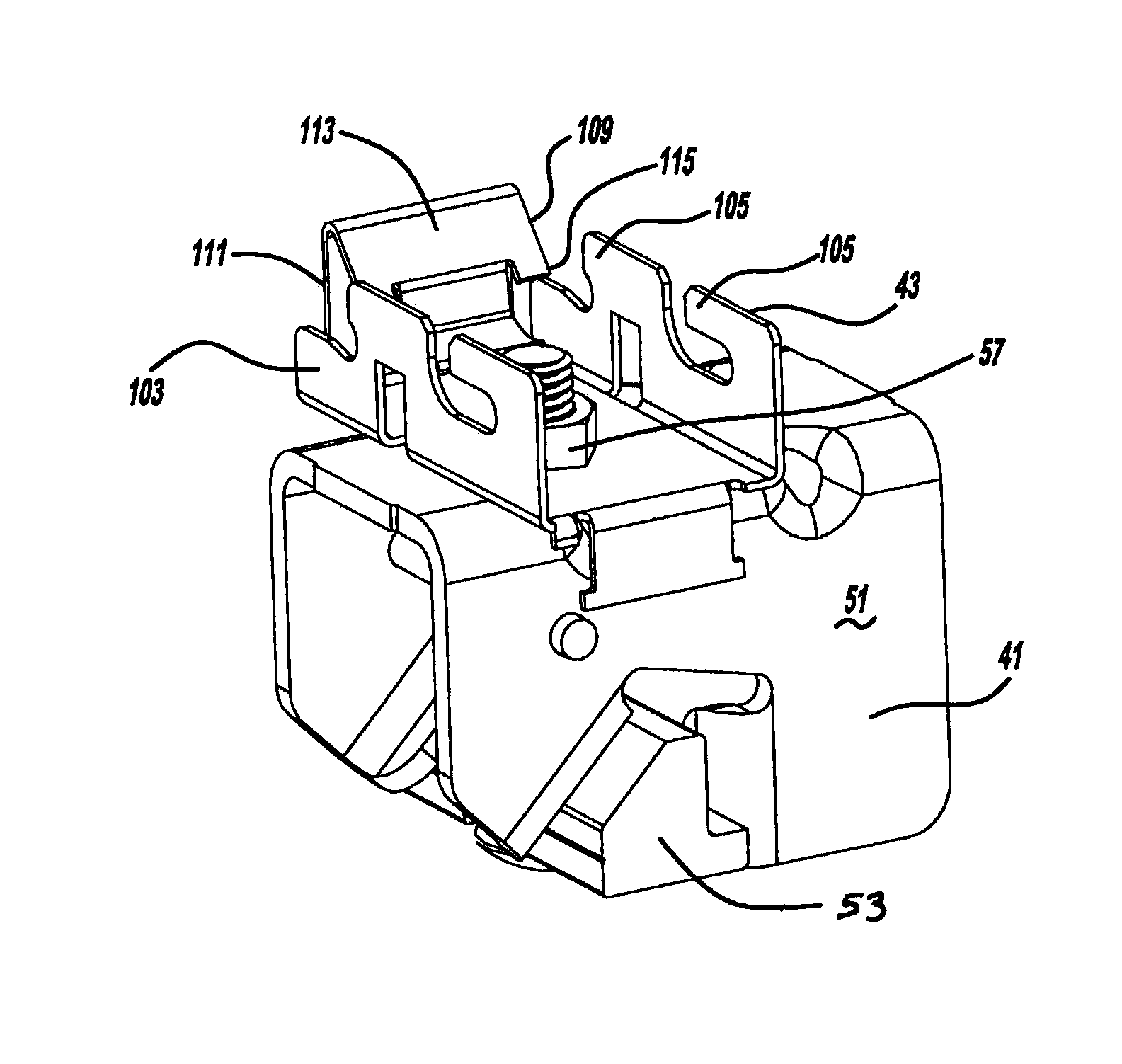
[0014]Referring to FIGS. 3, 4 and 5, each securing system 33 includes a roof clamp 41, a catc...


PUM


Abstract

A solar panel securing system is provided. In another aspect, a solar or photovoltaic panel assembly is mounted to a building roof in a screw-free manner. Another aspect employs a snap-in connection between a member pre-assembled to a solar panel and a roof-mounted bracket. A further aspect adhesively bonds a bracket directly to a glass surface of a solar panel. A method of securing a solar panel is additionally provided.

Description

BACKGROUND AND SUMMARY[0001]The present application relates generally to an attachment system and more particularly to a solar panel securing system for a building.[0002]Conventional photovoltaic or solar panels are mounted to roofs of buildings through screw-in clips or the like. Examples of such conventional devices are disclosed in U.S. Patent Publication No. 2011 / 0088740 entitled “Photovoltaic Panel Clamp” which published to Mittan et al. on Apr. 21, 2011, and U.S. Pat. No. 6,672,018 entitled “Solar Module Mounting Method and Clip” which issued to Shingleton on Jan. 6, 2004, both of which are incorporated by reference herein. Such conventional methods cause the installer to juggle many loose fasteners while simultaneously holding heavy solar panels and / or roof mounting components, often on a tilted metal roof in unpleasant weather conditions. Furthermore, such traditional multi-piece screw or bolt arrangements take considerable time to install while also having inconsistent inst...

Claims


Application Information

Patent Timeline
Patent Type & Authority Patents(United States)
IPC IPC(8): E04B2/30
CPCF24J2/5256F24J2/5203Y02E10/47Y02B10/20F24S25/30F24S2025/6002F24S2025/6004F24S25/634
Inventor DUPONT, LUCCHEUNG, BRIAN C.
Owner A RAYMOND & CO
Why Eureka
Try Eureka