Pivoting mechanism with gross and fine resistance adjustment

a technology of resistance adjustment and pivoting mechanism, which is applied in the direction of movable seats, seats, gearing, etc., can solve the problems of insufficient support of the same chair against pivoting, the resistance provided by the pivoting mechanism cannot be adjusted, and the chair provides far too much resistance. achieve the effect of maximum spa

Active Publication Date: 2014-05-06
CVEK SAVA
View PDF32 Cites 25 Cited by
  • Summary
  • Abstract
  • Description
  • Claims
  • Application Information

AI Technical Summary

Benefits of technology

[0007]A further object of embodiments of the invention is to provide a pivoting mechanism that permits fine resistance adjustment within each given resistance zone.
[0009]Yet another object of embodiments of the invention is to provide an adjustable pivoting mechanism that is compact in construction thereby to permit maximum space for internal and external components.

Problems solved by technology

Under certain constructions, the resistance provided by the pivoting mechanism cannot be adjusted.
Consequently, lighter users may find that a chair provides far too much resistance while heavier users are likely to find that the same chair provides insufficient support against pivoting.
However, the range over which the pivoting mechanism is adjustable is commonly limited so that not all users will be accommodated even where the full range of adjustment is exploited.
Furthermore, the adjustable pivoting mechanisms of the prior art typically require a continuous adjustment through the range of pivoting resistance.
This adjustment is time consuming and laborious.
In these and other circumstances requiring large adjustments in pivoting resistance, the user of a seat with a prior art pivoting mechanism must either undertake the tedious adjustment process or forego the desired support characteristics.

Method used


Image

  • Pivoting mechanism with gross and fine resistance adjustment
  • Pivoting mechanism with gross and fine resistance adjustment
  • Pivoting mechanism with gross and fine resistance adjustment

Examples


Embodiment Construction

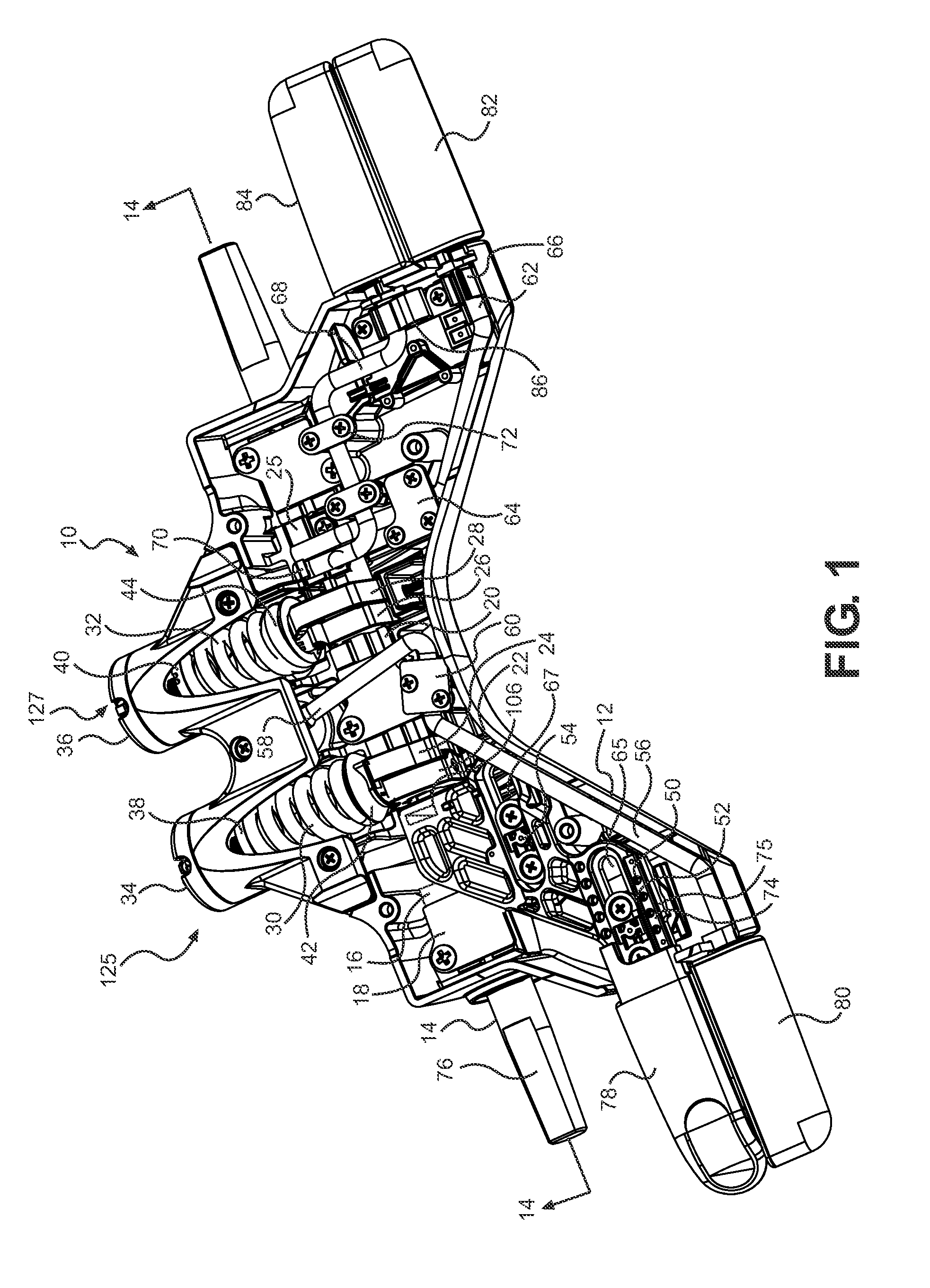
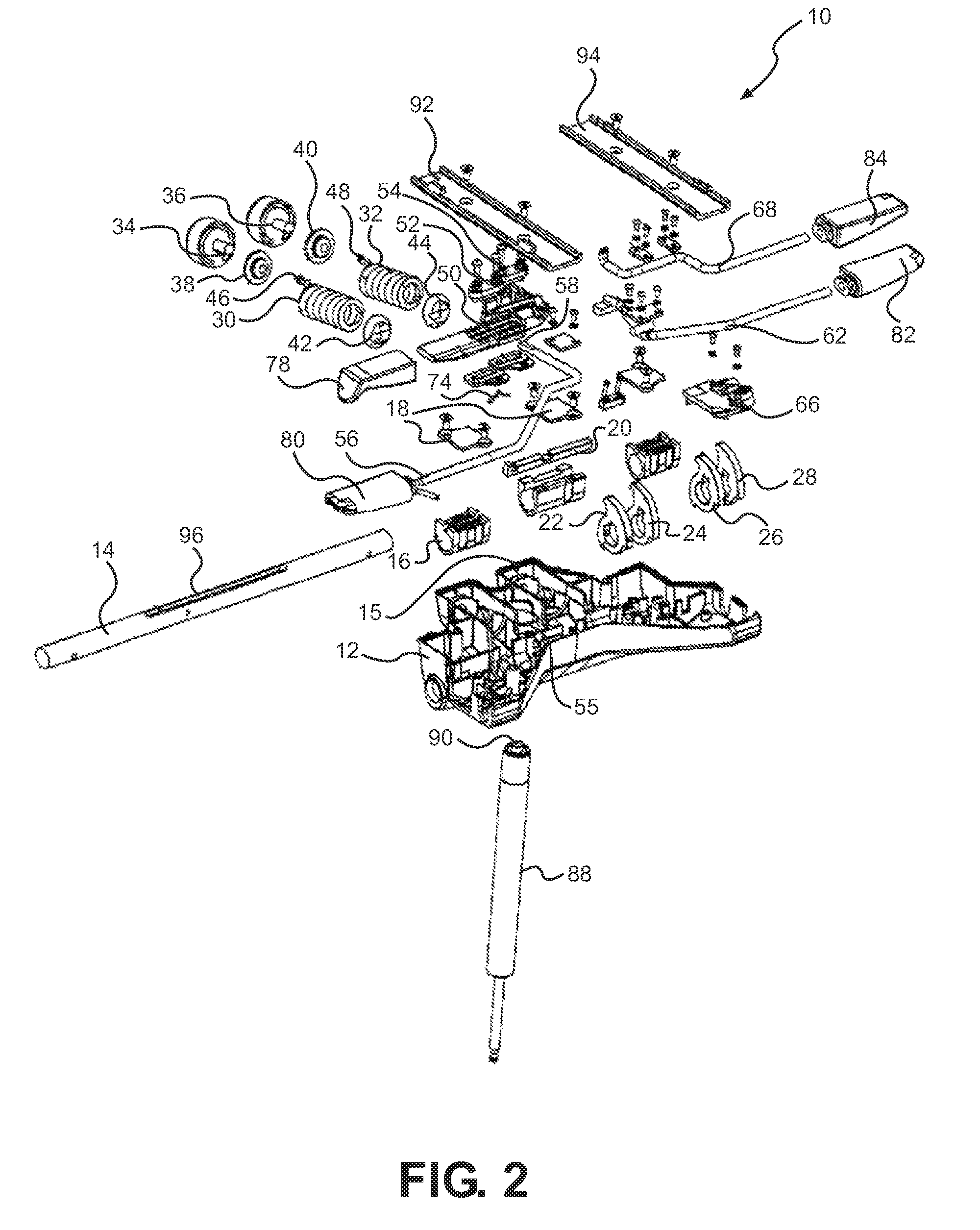
[0039]The adjustable pivoting mechanisms disclosed herein are subject to a wide variety of embodiments. However, to ensure that one skilled in the art will be able to understand and, in appropriate cases, practice the present invention, certain preferred embodiments of the broader invention revealed herein are described below and shown in the accompanying drawing figures.

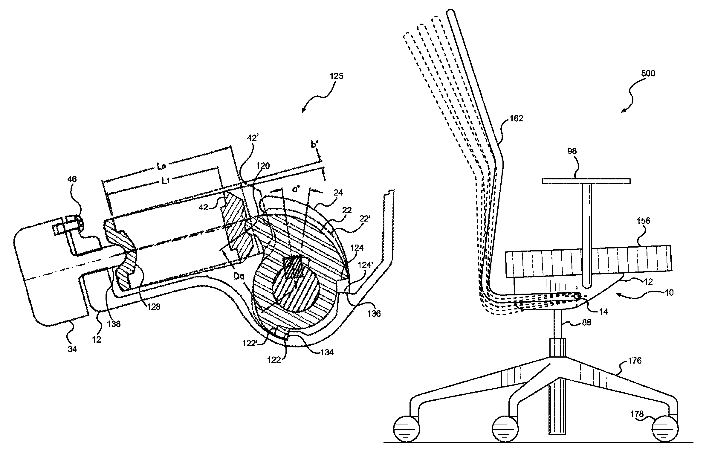
[0040]The pivoting mechanism disclosed herein is commonly depicted as being employed relative to a chair, and that application has been found to produce a chair construction that is particularly advantageous in structure and function. However, it is to be understood that the pivoting mechanisms could be employed in other applications within the scope of the invention except as it may be expressly limited. Therefore, before any particular embodiment of the invention is explained in detail, it must be made clear that the following details of construction and illustrations of inventive concepts are mere examples of the...


PUM


Abstract

A pivoting mechanism with gross and fine adjustment with a housing, an elongate shaft pivotally retained by the housing, resiliently deformable members retained by the housing, cam members coupled to the shaft wherein the cam members are disposed to deform the resiliently deformable members when the cam members are pivoted, and a locking slide bar for selectively causing the cam members to pivot with the shaft to produce gross adjustments in pivoting resistance. First and second ends of the shaft can act as an output interface for outputting the pivoting resistance exhibited by the shaft to a seat back structure, a seat bottom structure, or some other structure. A threaded rod rotated by a handle can adjust an initial deformation of the first resiliently deformable member for fine pivoting resistance adjustment.

Description

FIELD OF THE INVENTION[0001]The present invention relates generally to pivoting mechanisms. More particularly, disclosed herein are pivoting mechanisms capable of gross adjustment between multiple resistance zones and, potentially, fine adjustment within each resistance zone.BACKGROUND OF THE INVENTION[0002]Numerous chair designs have been proposed with a back structure retained to pivot in relation to a seat structure by a pivoting mechanism. Under certain constructions, the resistance provided by the pivoting mechanism cannot be adjusted. With this, large users, small users, and users with different preferences are provided with identical pivoting resistance. Consequently, lighter users may find that a chair provides far too much resistance while heavier users are likely to find that the same chair provides insufficient support against pivoting.[0003]In other constructions, the resistance provided by the pivoting mechanism can be adjusted over a given range of resistance. With thi...

Claims


Application Information

Patent Timeline
Patent Type & Authority Patents(United States)
IPC IPC(8): A47C1/024
CPCA47C7/441A47C3/026F16H25/18A47C7/443Y10T74/1896
Inventor CVEK, SAVA
Owner CVEK SAVA
Why Eureka
Try Eureka