Projector for preventing thermal deterioration of a light shielding member

a technology for preventing thermal deterioration and projectors, which is applied in the field of projectors, can solve the problems of thermal deterioration noticeable rise in temperature of light shielding plates, etc., and achieve the effect of reducing friction sound

Active Publication Date: 2014-05-06
SEIKO EPSON CORP
View PDF5 Cites 0 Cited by
  • Summary
  • Abstract
  • Description
  • Claims
  • Application Information

AI Technical Summary

Benefits of technology

[0008]An advantage of some aspects of the invention is to provide a projector with which it is possible to prevent a thermal deterioration of a light shielding plate used at a time of image mute.

Problems solved by technology

In particular, as an increase in luminance of the light source device has been promoted in recent years, there is a problem in that a rise in temperature of the light shielding plate becomes noticeable, and the light shielding plate thermally deteriorates.

Method used


Image

  • Projector for preventing thermal deterioration of a light shielding member
  • Projector for preventing thermal deterioration of a light shielding member
  • Projector for preventing thermal deterioration of a light shielding member

Examples


Embodiment Construction

[0036]Hereafter, a description will be given, based on the drawings, of one embodiment of the invention.

Configuration of Projector

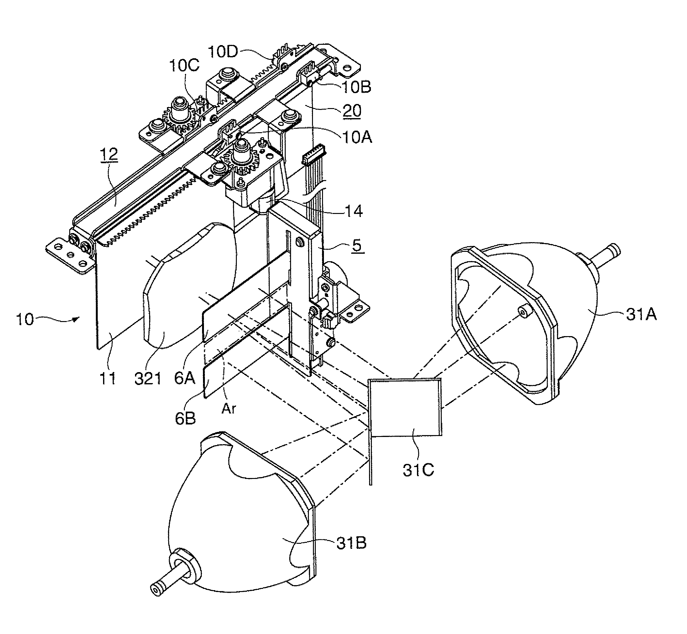
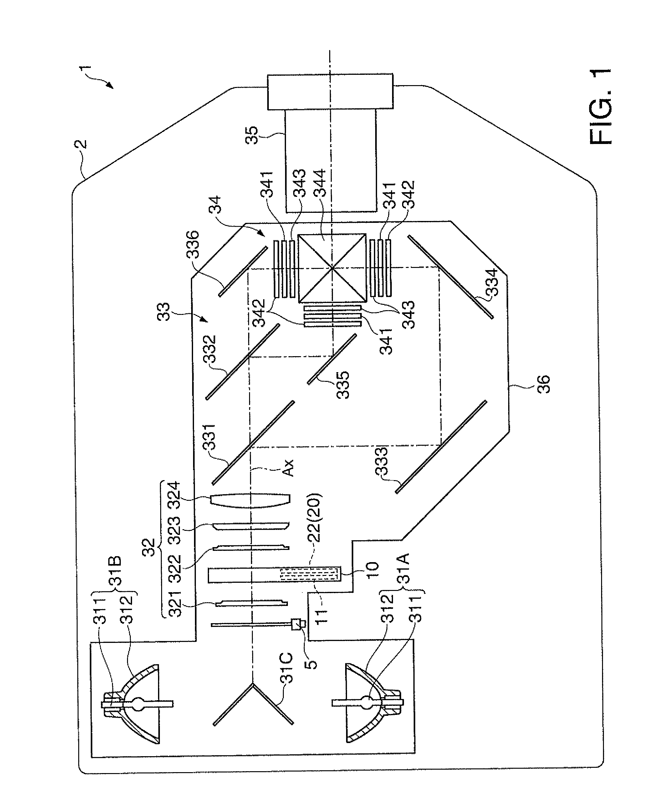
[0037]FIG. 1 is a diagram showing an outline configuration of a projector 1 of the embodiment.

[0038]Hereafter, for convenience of description, a side on which a projection lens 35 (FIG. 1) is disposed is taken to be a “front”, and the opposite side to be a “back”. Also, a “left” and “right”, to be described hereafter, respectively mean the “left” and “right” as seen from the back side.

[0039]The projector 1 forms an image according to image information, and projects it onto a screen (not shown). As shown in FIG. 1, the projector has a configuration such that an optical unit 3 and a control unit 4 (refer to FIG. 7) are housed inside an exterior housing 2.

Configuration of Optical Unit

[0040]The optical unit 3, under a control by the control unit 4, forms the image in accordance with the image information, and projects it.

[0041]As shown in FIG. 1, the optical ...


PUM


Abstract

A projector includes: a light source device; an optical modulation device configured to modulate a luminous flux emitted from the light source device in accordance with image information, forming an image; projection optical device configured to project the image; a shutter device including a light shielding plate which can move into and out of an optical path of the luminous flux ranging from the light source device to the optical modulation device, shields the luminous flux by the light shielding plate moving into the optical path; and a light control device which being disposed on the optical path's upstream side of the shutter device, changes the area of a light passage through which the luminous flux passes, controlling the quantity of the luminous flux.

Description

BACKGROUND[0001]1. Technical Field[0002]The present invention relates to a projector.[0003]2. Related Art[0004]In a projector, heretofore, a configuration has been known wherein, by using a light shielding plate, a projection image displayed on a screen, or the like, is temporarily put into nondisplay (hereafter described as image mute) (for example, refer to JP-A-2001-174910).[0005]In a projector described in JP-A-2001-174910, a movable light shielding plate is provided in one place inside the optical path of a luminous flux emitted from a light source device, and by causing the light shielding plate to operate, the luminous flux emitted from the light source device is shielded by the light shielding plate, setting the image mute.[0006]With the projector described in JP-A-2001-174910, as the image mute is set using the light shielding plate provided in the one place inside the optical path, the result being that approximately the whole of the luminous flux emitted from the light so...

Claims


Application Information

Patent Timeline
Patent Type & Authority Patents(United States)
IPC IPC(8): G03B21/14
CPCG03B21/142G03B9/14G03B21/2026G03B21/2013G03B21/2053
Inventor KITAHARA, WATARU
Owner SEIKO EPSON CORP
Why Eureka
Try Eureka