Liquid crystal display and liquid crystal projector

a liquid crystal display and projector technology, applied in non-linear optics, instruments, optics, etc., can solve the problems of leakage of light from the exit-side polarizing plate, difficult to solve both problems, and achieve the effect of preventing the deterioration of the light extinction ratio in the cross-nicol due to a diffraction of light, improving the viewing angle, and high accuracy

Active Publication Date: 2010-07-13
FUJIFILM CORP
View PDF12 Cites 0 Cited by
  • Summary
  • Abstract
  • Description
  • Claims
  • Application Information

AI Technical Summary

Benefits of technology

[0018]According to the present invention, even when light with various viewing angles enter the incident-side polarizing plate, the polarization planes of respective light become aligned with each other by the polarization azimuth compensator. Accordingly, a phase difference due to the liquid crystal layer can be compensated with high accuracy. Additionally, even when light is diffracted and diffuses due to the structure having the microstructures, the polarization azimuth compensator compensates the polarization plane according to the incident angle with respect to the exit-side polarizing plate. Therefore, deterioration of light extinction ratio in the cross-nicol due to a diffraction of light can be prevented. Thereby, leakage of light from the liquid crystal layer in the black display state can be suppressed to small, and the evenness of contrast, viewing angle, and brightness is improved. In particular, the liquid crystal display is further effective for preventing deterioration of light extinction ratio in a liquid crystal projector because the panel size of the liquid crystal display is small, and the pixel density thereof is high to form a high-resolution image.

Problems solved by technology

Accordingly, there causes one of reasons for impossibility of achieving a preferable light extinction ratio.
As a result, there arises a problem in which when part of light having passed through the incident-side polarizing plate passes through the exit-side polarizing plate, its incident angle on the latter is varied to cause leakage of light from the exit-side polarizing plate.
This problem occurs in addition to the problem of viewing angle dependency of the polarizing plate based on the azimuth angle of incidence described above, thus making it difficult to solve both problems.

Method used


Image

  • Liquid crystal display and liquid crystal projector
  • Liquid crystal display and liquid crystal projector
  • Liquid crystal display and liquid crystal projector

Examples


Embodiment Construction

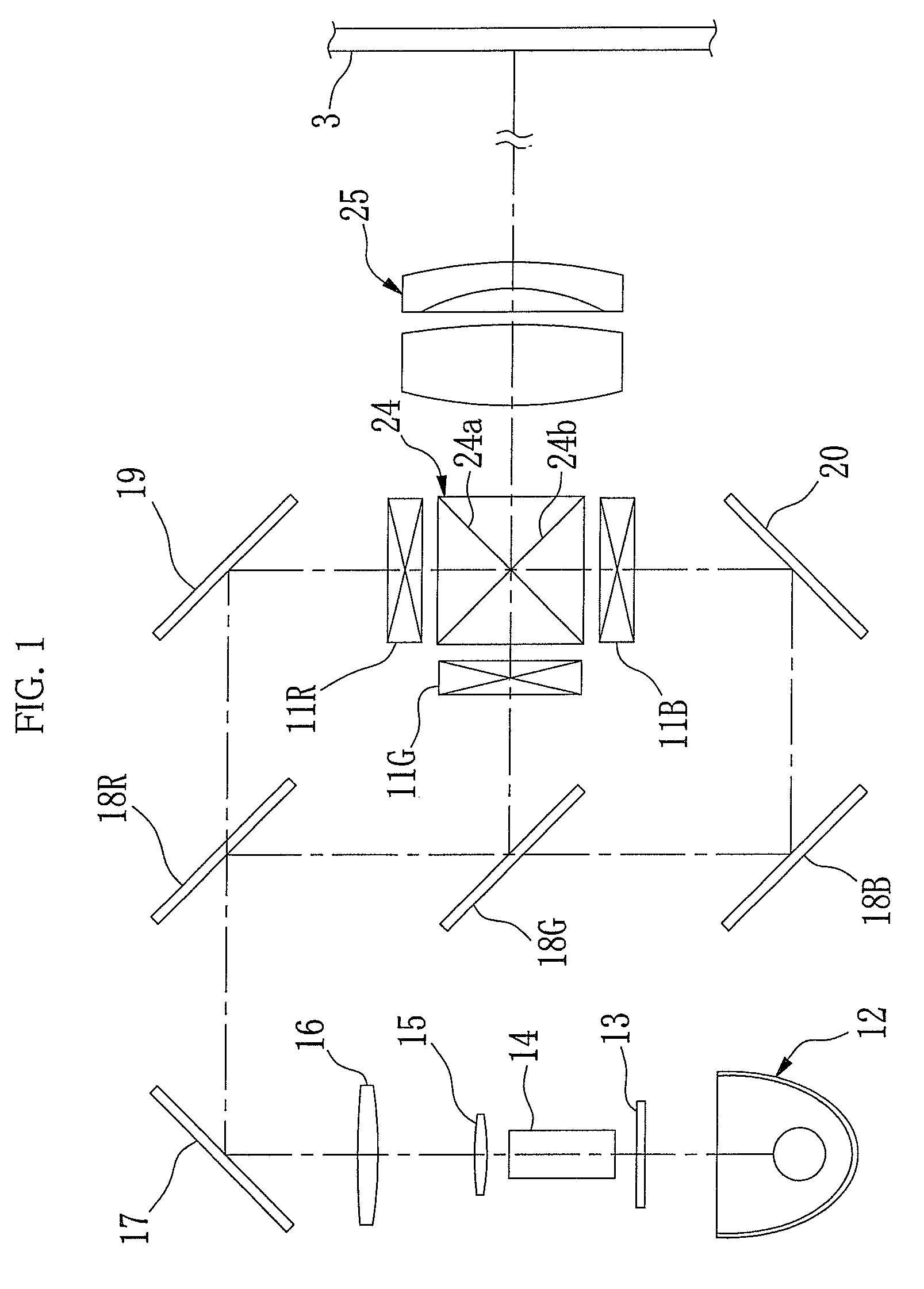
[0022]As shown in FIG. 1, a liquid crystal projector 10 includes three transmissive-type liquid crystal display panels 11R, 11G, and 11B to project a full color image on a screen 3. White light emanated from a light source 12 passes through a filter 13 that blocks ultraviolet rays and infrared rays. An end surface of a glass rod 14 is located at the vicinity of a focal point of an ellipsoidal mirror for use in the light source 12. White light emanated from the light source 12 passes through the glass rod 14, thus resulting in a uniform intensity distribution.

[0023]The white light emanated from the glass rod 14 is collimated by a relay lens 15 and a collimate lens 16. The collimated light enters a mirror 17. The white light reflected by the mirror 17 enters a dichroic mirror 18R that transmits red light. After passing through the dichroic mirror 18R, the red light is reflected by a mirror 19 to illuminate the liquid crystal display panel 11R from behind.

[0024]The green light and blue...


PUM

PropertyMeasurementUnit
polar angleaaaaaaaaaa
transparentaaaaaaaaaa

Abstract

A polarization azimuth compensation layer (31) is effective in aligning a polarization plane of light obliquely entering an incident-side polarizing plate (30) with a polarization plane of light entering the incident-side polarizing plate (30) in a direction of a normal line. A retardation compensation layer (41) is disposed nearer a liquid crystal layer (34) than a microlens array (40) diffracting part of incident light, to compensate a phase difference due to the liquid crystal layer (34). Diffracted light caused by the microlens array (40) and a TFT circuit pattern (46) enters a polarization azimuth compensation layer (36). The polarization azimuth compensation layer (36) prevents leakage of light by aligning a polarization plane of the diffracted light to be parallel to an absorption axis of an exit-side polarizing plate (37).

Description

TECHNICAL FIELD[0001]The present invention relates to a liquid crystal display in which a liquid crystal cell is disposed between a pair of polarizers arranged in a cross-nicol or a parallel nicol, and to a liquid crystal projector utilizing the liquid crystal display.BACKGROUND ART[0002]A liquid crystal cell which performs light modulation with use of optical rotatory property and birefringence in liquid crystal molecules is combined with a polarizing plate (including a polarizing film). The polarizing plate decomposes the incident non-polarized light to two polarized light components which are perpendicular to each other. Further the polarizing plate blocks light of the polarized light component parallel to an absorption axis, and transmits light of the polarized light component perpendicular to the absorption axis. In a transmissive liquid crystal cell, the polarizing plates are disposed at both a light incident surface side and a light exit surface side of the liquid crystal cel...

Claims


Application Information

Patent Timeline
Patent Type & Authority Patents(United States)
IPC IPC(8): G02F1/13363
CPCG02F1/133634G02F2001/133607G02F1/133607
Inventor NAKAGAWA, KENICHI
Owner FUJIFILM CORP
Why Eureka
Try Eureka