A flow cytometry chip

A technology for detecting chips and flow cells, which is applied in measuring devices, particle and sedimentation analysis, individual particle analysis, etc. It can solve problems affecting the use of chips and large volume, and achieve convenient quality inspection, small chip size, and stable liquid environment Effect

Active Publication Date: 2020-08-07
JIANGSU JIM BIO SCI & TECH
View PDF12 Cites 0 Cited by
  • Summary
  • Abstract
  • Description
  • Claims
  • Application Information

AI Technical Summary

Problems solved by technology

Sample focusing is the key technology of flow particle detection. In the current detection, chips that focus on the sample liquid through external force are used. This type of chip integrates the detection electrodes in the chip, which has a large volume and is provided by negative pressure during use. Power, and it is necessary to add buffer to the chip when using it. How and how much buffer is added will also affect the use of the chip

Method used


Image

  • A flow cytometry chip
  • A flow cytometry chip
  • A flow cytometry chip

Examples


Embodiment 1

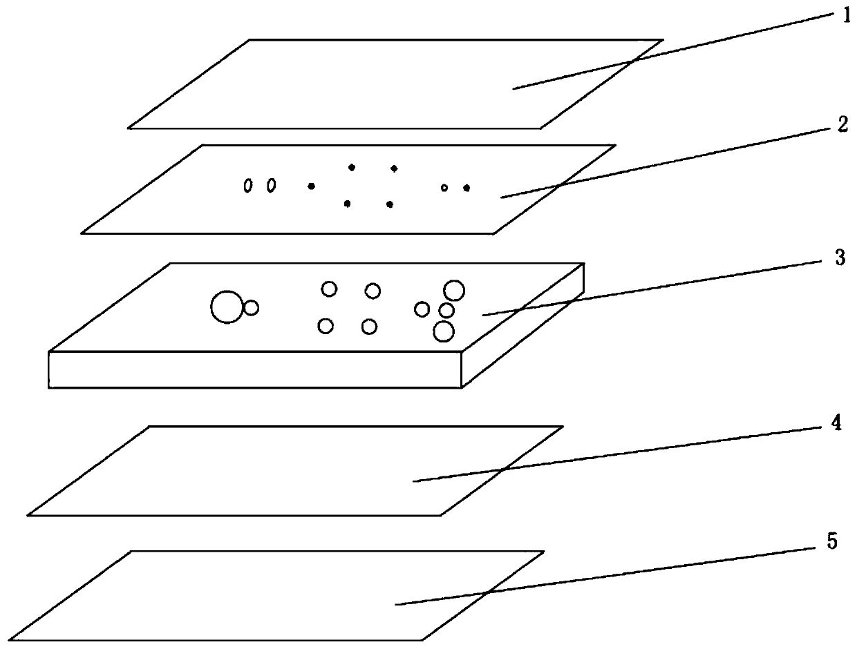
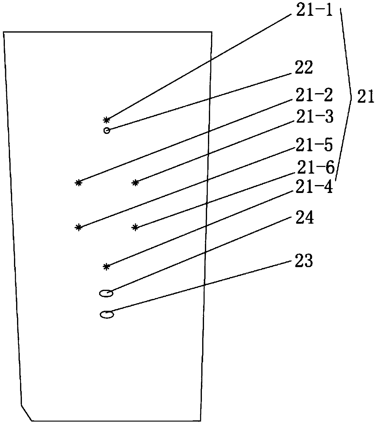
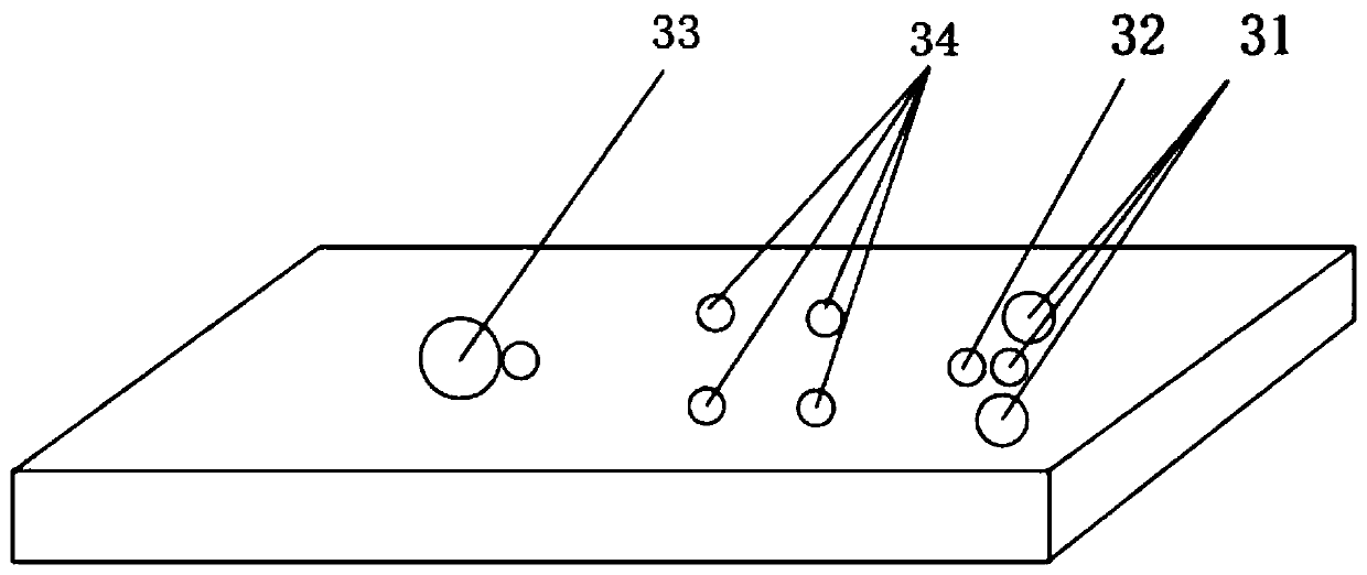
[0029] see figure 1 , figure 2 with image 3 , The flow cytometry detection chip of this embodiment is compounded with a peelable first protective film 1, a first sealing film 2, a microfluidic chip 3, a second sealing film 4, and a second protective film sequentially from top to bottom 5; The first sealing membrane 2 is provided with six electrode holes 21, a sample hole 22 and a gas outlet 23; the microfluidic chip 3 is provided with a connected liquid reservoir 31 and a gas outlet from top to bottom according to the use direction of the chip. The sample cell 32, the detection channel and the waste liquid pool 33, and two pairs of four detection holes 34 located at the two ends of the detection channel; the six electrode holes 21 are arranged at positions corresponding to the first electrode holes 21- of the liquid reservoir 31 1. The second electrode hole 21-2, the third electrode hole 21-3, the fifth electrode hole 21-5, the sixth electrode hole 21-6 corresponding to the f...


PUM


Abstract

The invention discloses a fluidic cell detection chip. A first protection film, a first sealing film, a microfluidic chip and a second sealing film which are strippable are sequentially composited from top to bottom; the first sealing film is provided with at least four electrode holes, one sample adding hole and one vent hole; a liquid storage tank, a sample adding tank, a detection channel and a waste liquid tank which are communicated and at least two detection holes located at the two ends of the detection channel are arranged on the microfluidic chip in the use direction of the chip from top to bottom; the setting positions of the four electrode holes correspond to the liquid storage tank, two detection holes and an inlet of the waste liquid tank respectively; the setting position of the sample adding hole corresponds to the sample adding tank, and the setting position of the vent hole corresponds to the waste liquid tank. According to the fluidic cell detection chip, power for liquid flow is provided by means of a gravity principle, and therefore a drive does not need to be additionally arranged; the chip is small in size and low in cost, and miniaturization and energy conservation of equipment used in the detection process are achieved; meanwhile, the electrode holes are arranged for sampling detection, and the accuracy of a detection result is guaranteed.

Description

Technical field [0001] The invention relates to a flow cell detection chip. Background technique [0002] Flow particle detection is a technique for quantitative analysis and sorting of particles in liquid one by one. It can measure particle size, shape, concentration, activity, etc. It is widely used in hematology, immunology, molecular biology and other disciplines. Applications. The Coulter principle used in its detection refers to: when the particles suspended in the electrolyte pass through the small hole with the electrolyte, it replaces the same volume of the electrolyte, resulting in a constant current design circuit between the two electrodes inside and outside the small hole. The resistance changes instantaneously and generates a potential pulse. The size and frequency of the pulse signal are proportional to the size and number of particles. Sample focusing is the key technology of flow particle detection. Current detection uses chips that focus on the sample liquid b...

Claims


Application Information

Patent Timeline
Patent Type & Authority Patents(China)
IPC IPC(8): G01N15/14
CPCG01N15/14
Inventor 沙俊帅宇阎玉川董健朱必茹
Owner JIANGSU JIM BIO SCI & TECH
Why Eureka
Try Eureka