Lamp

a technology for lamps and light sources, applied in the field of lamps, to achieve the effect of enhancing the convenience of assembly

Inactive Publication Date: 2014-05-06
SUNONWEALTH ELECTRIC MACHINE IND
View PDF20 Cites 0 Cited by
  • Summary
  • Abstract
  • Description
  • Claims
  • Application Information

AI Technical Summary

Benefits of technology

[0006]It is therefore the objective of this invention to provide a lamp convenient in carrying out the electrical connection between a circuit board and a cooling fan, so as to enhance the assembling convenience thereof.
[0007]It is another objective of this invention to provide a lamp enabling a cooling fan to directly dissipate the heat generated by a circuit board, so as to increase the lifetime of the lamp.

Problems solved by technology

However, there are some problems shown in the following when the conventional lamp 9 is in use.

Method used


Image

  • Lamp
  • Lamp
  • Lamp

Examples


Embodiment Construction

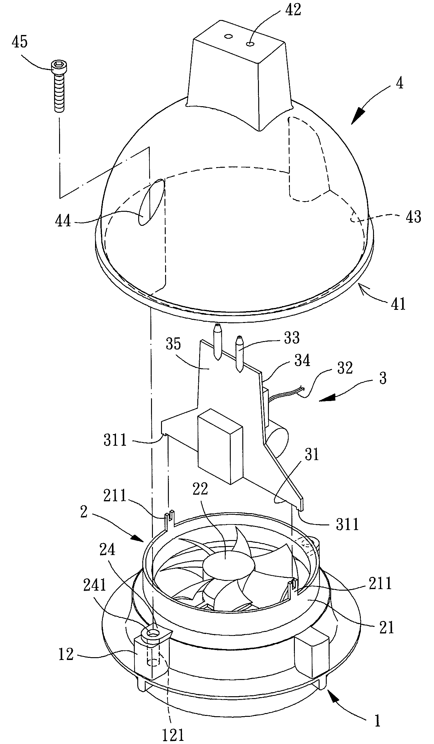
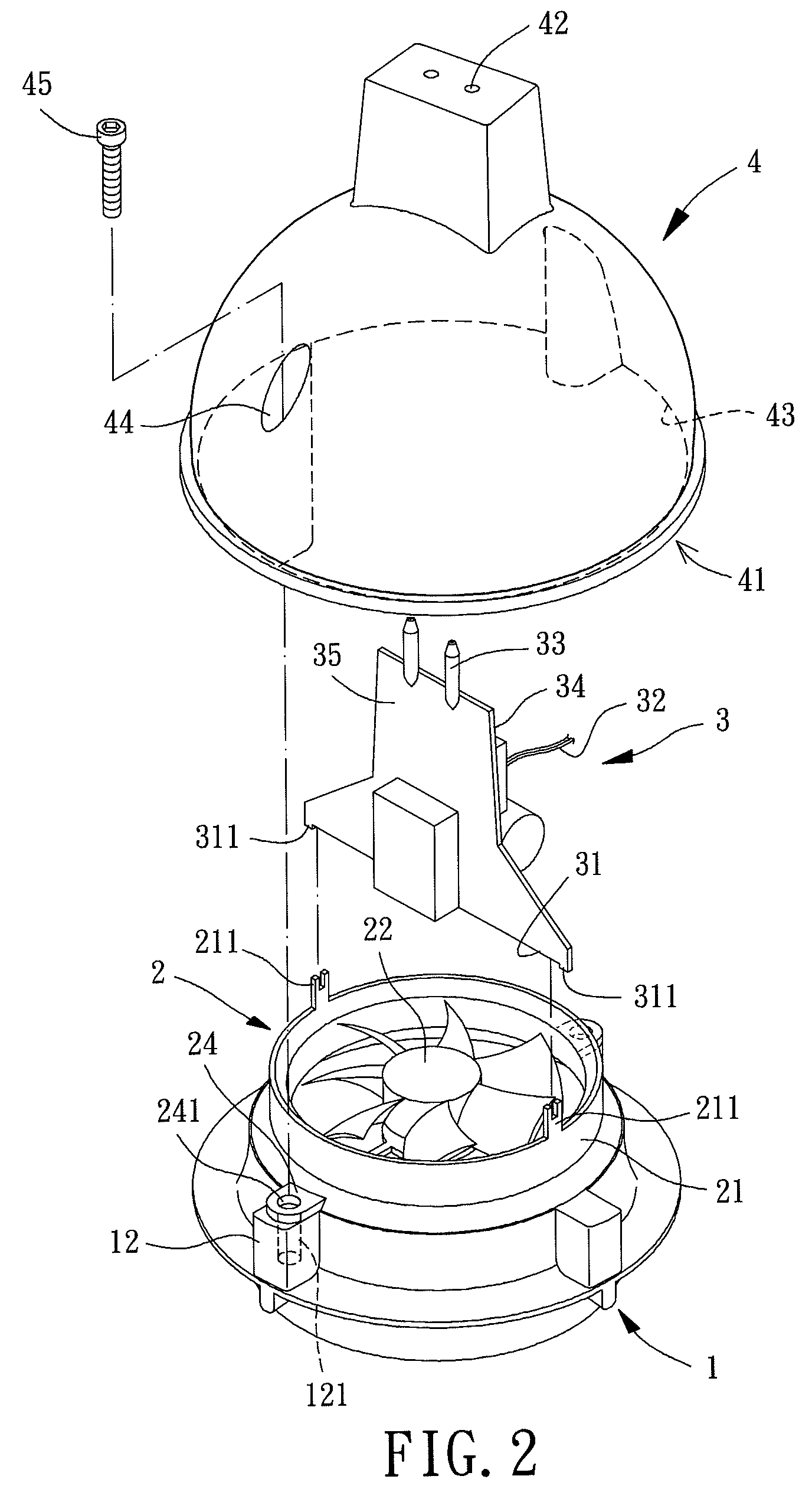
[0029]Referring to FIGS. 2, 3 and 4, a first embodiment of a lamp of this invention is shown, which includes a base 1, a cooling fan 2 and a circuit board 3. The base 1 is adapted to support the cooling fan 2. The circuit board 3 couples with the cooling fan 2 and is capable of connecting with an external power source, and thus the circuit board 3 can drive the cooling fan 2 by electrical power provided by the power source. Consequently, airflows driven by the cooling fan 2 can cool the heat in this lamp, such as the heat generated by the circuit board 3.

[0030]Specifically, there is a LED member 11 mounted on the base 1 powered by the circuit board 3 or the external power source for illumination. The base 1 can further provide a coupling portion 12 for the cooling fan 2 to mount on, with the coupling portion 12 in a form that is able to couple with the cooling fan 2, such as a buckling, screwing or adhesion structure. In this embodiment, the base 1 is made of heat conductive materia...


PUM


Abstract

A lamp includes a base, a cooling fan and a circuit board. The base has a coupling portion, with a LED member mounted on the base. The cooling fan has a frame coupled with the coupling portion of the base, wherein the frame receives a driving unit and a fan wheel coupling with the driving unit in a rotatable way and has a first fixing portion. The circuit board has a second fixing portion coupling with the first fixing portion of the frame, with the circuit board electrically connecting with the driving unit of the cooling fan.

Description

BACKGROUND OF THE INVENTION[0001]1. Field of the Invention[0002]The present invention generally relates to a lamp and, more particularly, to a lamp having a cooling fan to cool a circuit board in the lamp.[0003]2. Description of the Related Art[0004]Referring to FIG. 1, an invention of Taiwan Patent No. I327633, entitled as “LED Lamp,” is shown. The invention is about a conventional lamp 9 including a body 91, a circuit board 92, a connecting unit 93 and an illuminating unit 94. The body 91 has a plurality of air inlets 911. The circuit board 92 has a plurality of through holes 921. The connecting unit 93 has a plurality of coupling tubes 931 aligning with the through holes 921 of the circuit board 92. The illuminating unit 94 has a fan 941 mounted on a heat sink 942, with the heat sink 942 coupling with a LED member 943 for the fan 941 and heat sink 942 to cool the LED member 943.[0005]However, there are some problems shown in the following when the conventional lamp 9 is in use. F...

Claims


Application Information

Patent Timeline
Patent Type & Authority Patents(United States)
IPC IPC(8): F21V29/02
CPCF21V23/006F21Y2101/02F21V29/2275F21K9/137F21V19/0005F21V29/02F21V29/80F21K9/233F21Y2115/10F21V29/67
Inventor HUANG, KUO-HAOCHOU, WEN-NAN
Owner SUNONWEALTH ELECTRIC MACHINE IND
Why Eureka
Try Eureka