Light guide plate of display apparatus

a technology of light guide plate and display apparatus, which is applied in the direction of lighting and heating apparatus, planar/plate-like light guide, instruments, etc., can solve the problems of substantial reduction of power consumption and slimness, and achieve the effect of substantially improving the display quality of the display apparatus and substantially reducing the dark areas of the light guide pla

Active Publication Date: 2014-05-06
SAMSUNG DISPLAY CO LTD
View PDF11 Cites 3 Cited by
  • Summary
  • Abstract
  • Description
  • Claims
  • Application Information

AI Technical Summary

Benefits of technology

[0008]Exemplary embodiments of the invention provide a display apparatus with improved display quality and reduced light loss.
[0012]In an exemplary embodiment, the light emitted passing through the optical recess from the light source has rectangular brightness distribution such that an exit light distribution of the light guide plate has the exit light distribution in a rectangular shape. Thus, dark areas of the light guide plate are substantially reduced, and display quality of the display apparatus is thereby substantially improved.

Problems solved by technology

However, the point light source typically has substantially reduced power consumption and slimness.

Method used


Image

  • Light guide plate of display apparatus
  • Light guide plate of display apparatus
  • Light guide plate of display apparatus

Examples


Embodiment Construction

[0040]Hereinafter, exemplary embodiments of the invention will be explained in detail with reference to the accompanying drawings.

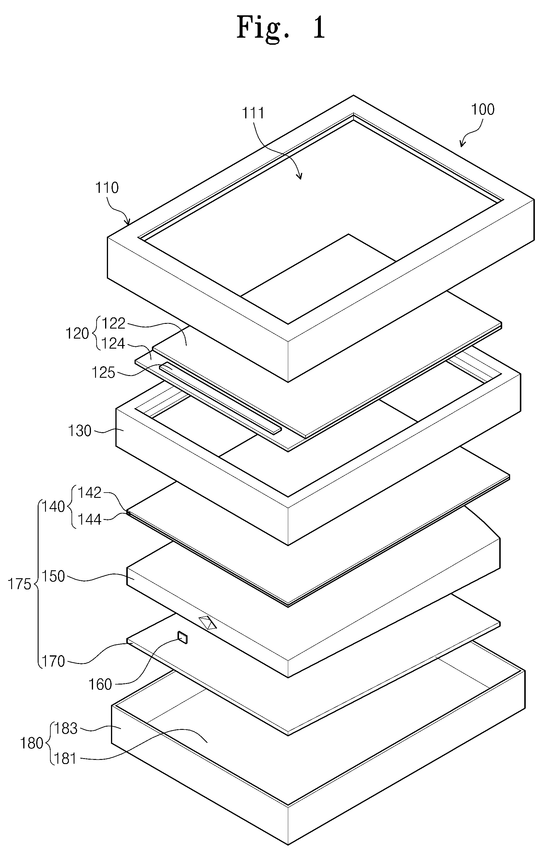
[0041]FIG. 1 is an exploded perspective view of an exemplary embodiment of a display apparatus according to the invention.

[0042]Referring to FIG. 1, a display apparatus 100 includes a display panel 120, a mold frame 130, a backlight assembly 175, a bottom chassis 180, and a top chassis 110.

[0043]The display panel 120 displays an image on one surface thereof. The display panel 120 is not a self-emissive device and may be various display panels, such as a liquid crystal display panel and an electrophoretic display panel, for example. Hereinafter, an exemplary embodiment where the display panel 120 is a liquid crystal display panel will be described in detail.

[0044]The display panel 120 has a rectangular plate-like shape. The display panel 120 includes a first substrate 122, a second substrate 124, and a liquid crystal layer (not shown) interposed between th...


PUM


Abstract

A display apparatus includes a light source and a light guide plate including a light incident surface facing the light source and which receive the light, an opposite surface opposite to the light incident surface and which reflects the light and has an arc shape, connection surfaces at opposing sides of the light incident surface and which connect the light incident surface and the opposite surface, an upper surface connected to the light incident surface, the opposite surface and the connection surfaces and which outputs the light, and a lower surface opposite to the upper surface. The light incident surface of the light guide plate includes a first surface extending in a predetermined direction, and second surfaces inclined from the first surface in an area corresponding to the light source such that an optical recess having a polygonal pyramid shape is defined by the second surfaces.

Description

[0001]This application claims priority to Korean Patent Application No. 10-2011-0047453, filed on May 19, 2011, and all the benefits accruing therefrom under 35 U.S.C. §119, the content of which in its entirety is herein incorporated by reference.BACKGROUND OF THE INVENTION[0002]1. Field of the Invention[0003]Exemplary embodiments of the invention relate to a display apparatus. More particularly, exemplary embodiments of the invention relate to a display apparatus with improved display quality and reduced light loss.[0004]2. Description of the Related Art[0005]A liquid crystal display typically includes a display panel which displays an image and a backlight unit that provides light to the display panel.[0006]The backlight unit includes a light source that emits light and a light guide plate that guides the light to the display panel. As the light source, a line light source such as a cold cathode fluorescent lamp or a point light source such as a light emitting diode is used. The l...

Claims


Application Information

Patent Timeline
Patent Type & Authority Patents(United States)
IPC IPC(8): F21V8/00F21V7/09
CPCG02B6/0028G02B6/0016G02B6/002G02B6/0031G02F1/1336G02F1/133603G02F1/133611
Inventor KIM, GUK HYUNPRUDNIKOV, OLEGKIM, YOUNGCHANCHEONG, BYOUNGHO
Owner SAMSUNG DISPLAY CO LTD
Why Eureka
Try Eureka