Canister for transporting and/or storing radioactive materials conferring enhanced heat transfer

a radioactive material and canister technology, applied in the direction of nuclear elements, instruments, manufacturing tools, etc., can solve the problems of reducing the clearance between the radiological protection components and the shells, affecting the assembly, and reducing the thermal conductivity of the latter. , to achieve the effect of facilitating the assembly

Inactive Publication Date: 2014-05-06
TN INT (FR)
View PDF8 Cites 0 Cited by
  • Summary
  • Abstract
  • Description
  • Claims
  • Application Information

AI Technical Summary

Benefits of technology

[0017]Thus, the particular geometry and arrangement of the radiological protection components make it possible to confer to the lateral body of the canister a satisfactory thermal conductivity. The presence of helium or heat conduction fins is thus no longer necessary, which makes it possible to have a canister of simplified design and manufacture.
[0038]Finally, another object of the invention is a method for producing a canister as described above, in which each first and second metal radiological protection components are inserted into said annular space, then a tightening is carried out making it possible to constrain said components along the circumferential direction.

Problems solved by technology

The observed discontinuity of material has the effect of a considerable decrease in the thermal conductivity of the lateral body of the canister, implying a low capacity of the latter to dissipate the heat produced by the fuel assemblies.
To minimise the negative impact of the discontinuities of material, the clearances between the radiological protection components and the shells may be reduced by lessening the manufacturing tolerances, but this proves nevertheless to be very costly, and does not in the least enable the discontinuities of material to be eliminated.
However, this technique induces a cost and poses serious problems of operating the canister.
Nevertheless, this further complicates the design of the canister, and moreover necessitates the use of particular techniques to ensure that the fins are indeed in contact with each of the two shells of the lateral body.

Method used


Image

  • Canister for transporting and/or storing radioactive materials conferring enhanced heat transfer
  • Canister for transporting and/or storing radioactive materials conferring enhanced heat transfer
  • Canister for transporting and/or storing radioactive materials conferring enhanced heat transfer

Examples


Embodiment Construction

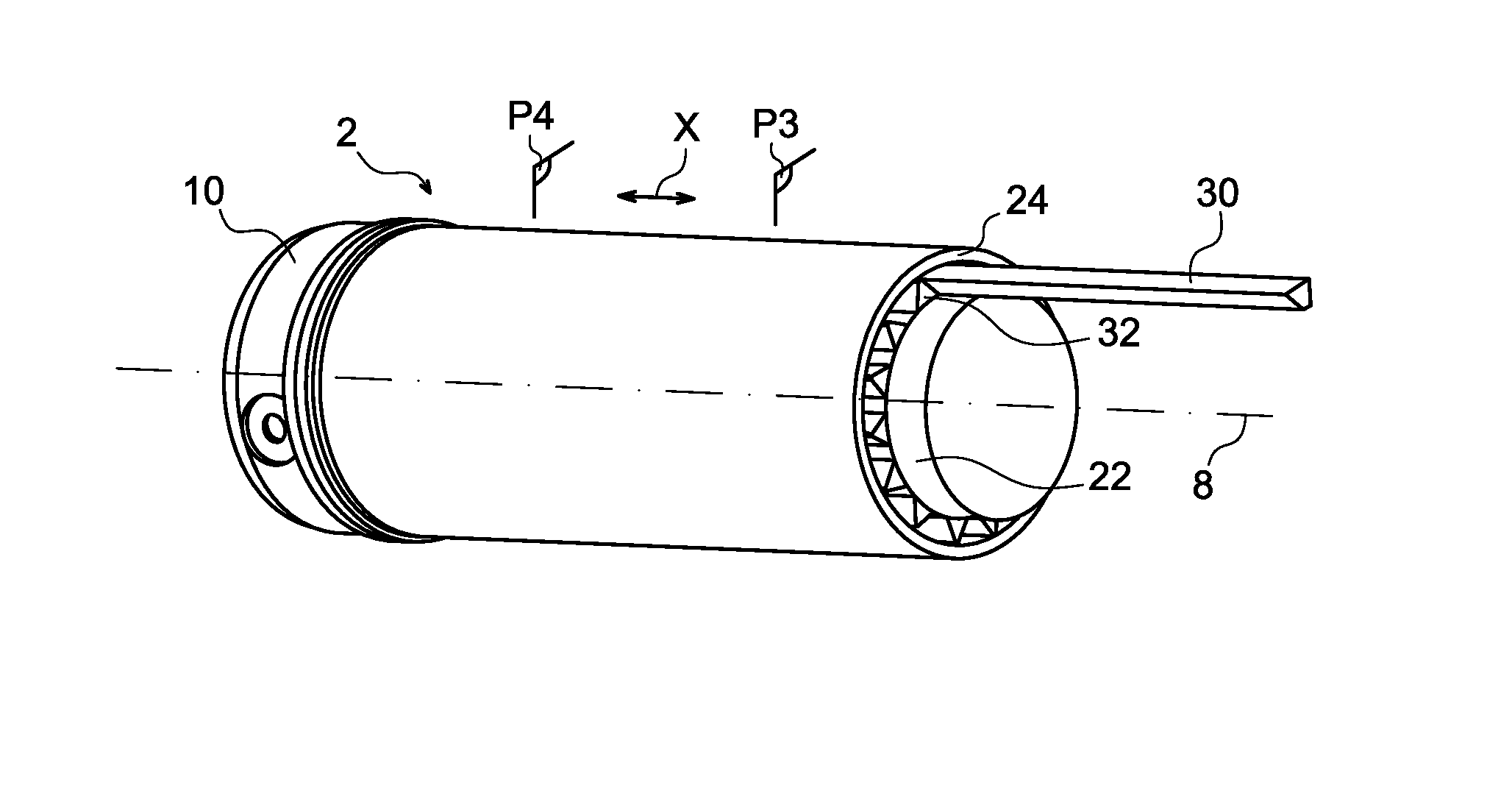
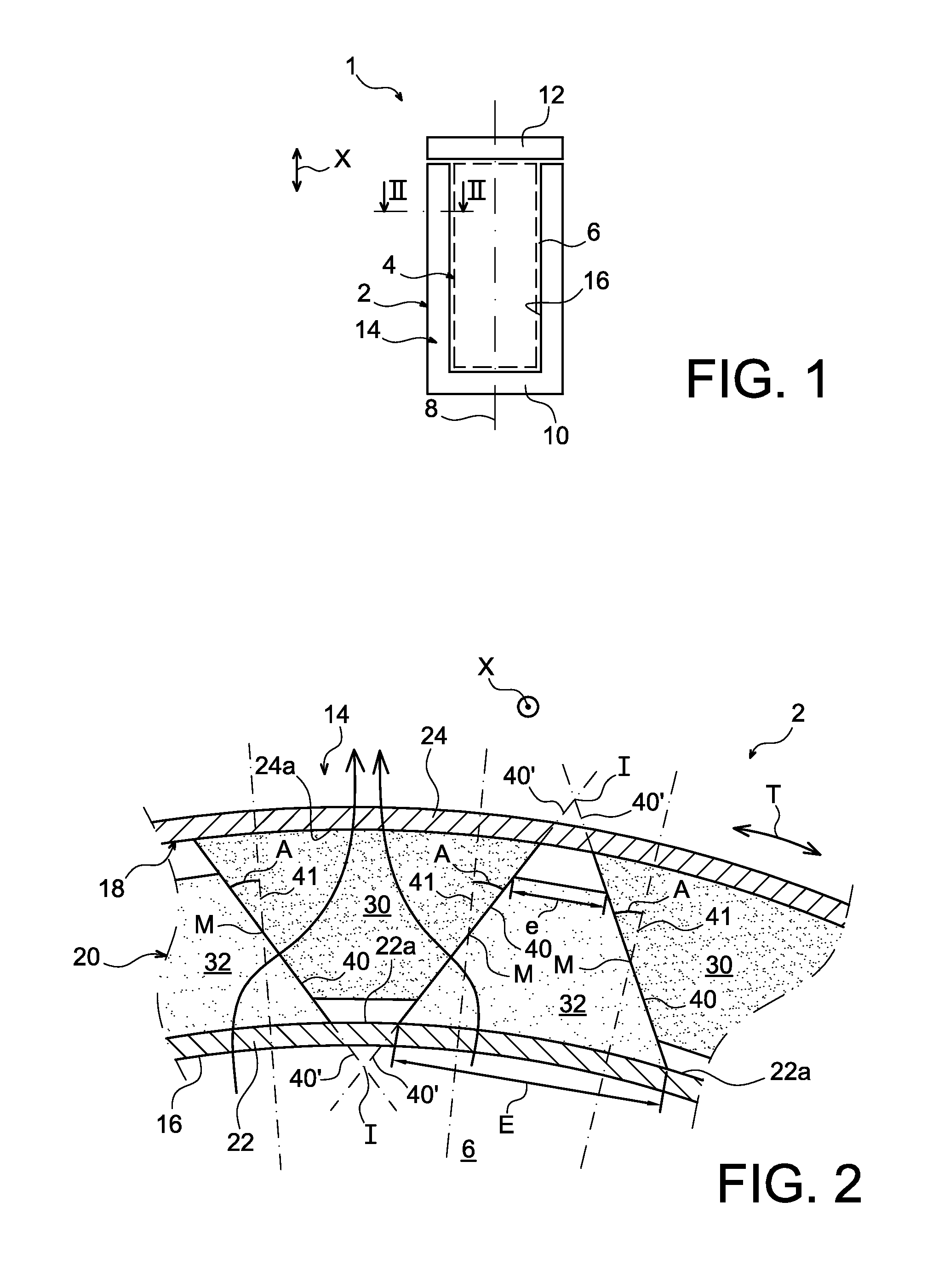
[0052]Firstly with reference to FIG. 1, a container 1 for transporting and / or storing nuclear fuel assemblies may be seen. It is in this respect recalled that the invention is in no way limited to the transport / storage of this type of nuclear material.

[0053]The container 1 overall comprises a canister 2, object of the present invention, inside of which is a storage device 4, also known as storage basket. The device 4 is provided to be placed in a cavity for housing 6 the canister 2, as shown schematically in FIG. 1, in which it is also possible to perceive the longitudinal axis 8 of this canister, merged with the longitudinal axes of the storage device and the housing cavity.

[0054]Throughout the description, the term “longitudinal” must be understood as parallel to the longitudinal axis 8 and to the longitudinal direction X of the canister, and the term “circumferential” must be understood as orthogonal to this same longitudinal axis 8, as well as to a transversal direction of the c...


PUM

PropertyMeasurementUnit
angleaaaaaaaaaa
angleaaaaaaaaaa
angleaaaaaaaaaa

Abstract

A canister for transporting and / or storing radioactive materials, the canister comprising two concentric shells between which is housed a radiological protection device comprising at least a first and a second metal components adjacent along a circumferential direction. According to the invention, the first component is supported against the outer shell and at a distance from the inner shell, whereas the second component is supported against the shell and at a distance from the shell. In addition, the components are in contact with each other along an interface taking, in section along any plane orthogonal to the longitudinal axis and crossing this interface, the form of a straight line segment defining with a radial straight line crossing it at its centre an acute angle (A).

Description

CROSS REFERENCE TO RELATED APPLICATIONS OR PRIORITY CLAIM[0001]This application claims priority of French Patent Application No. 09 57929, filed Nov. 10, 2009.DESCRIPTION[0002]1. Technical Field[0003]The present invention relates to the field of transporting and / or storing radioactive materials, such as nuclear fuel assemblies, fresh or irradiated.[0004]In particular, the invention relates to a canister comprising a radiological protection device laid out between two concentric shells, forming a barrier against gamma radiation.[0005]2. State of the Prior Art[0006]Conventionally, to ensure the transport and / or the storage of nuclear fuel assemblies, storage devices, also known as storage “baskets” or “racks”, are used. These storage devices, normally of cylindrical shape and of substantially circular section, have a plurality of adjacent housings each of which is able to receive a nuclear fuel assembly. The storage device is intended to be housed in the cavity of a canister so as to ...

Claims


Application Information

Patent Timeline
Patent Type & Authority Patents(United States)
IPC IPC(8): G21F1/08G21F5/00
CPCG21F5/008G21F3/00G21F5/10Y10T29/49826
Inventor BARDON, OLIVIERFOUSSARD, GUILAUMEKITSOS, STAVROS
Owner TN INT (FR)
Why Eureka
Try Eureka