Method for forming hydrophobic electrically conductive microporous layer for use as gas-diffusion layer

A gas diffusion layer, microporous layer technology, used in climate sustainability, electrical circuits, fuel cells, etc., to solve problems such as surface inhomogeneity

Pending Publication Date: 2020-12-22
COMMISSARIAT A LENERGIE ATOMIQUE ET AUX ENERGIES ALTERNATIVES
View PDF15 Cites 1 Cited by
  • Summary
  • Abstract
  • Description
  • Claims
  • Application Information

AI Technical Summary

Problems solved by technology

This variant embodiment of forming a hydrophobic conductive microporous layer may itself raise concerns about the surface non-uniformity of the layer

Method used


Image

  • Method for forming hydrophobic electrically conductive microporous layer for use as gas-diffusion layer
  • Method for forming hydrophobic electrically conductive microporous layer for use as gas-diffusion layer
  • Method for forming hydrophobic electrically conductive microporous layer for use as gas-diffusion layer

Examples


Embodiment 1

[0087] Synthesis of Poly(2,3,4,5,6-Pentafluorostyrene)(PPFS)

[0088] In a round bottom flask, 500 μl of TiCl 4 Added to 6ml of toluene. The catalyst was prepared by adding dropwise thereto 750 μl of a solution of triethylaluminum in 6 ml of toluene. The mixture was allowed to stabilize for 30 minutes.

[0089] Subsequently, 1.5 ml of TiCl will be formed 4 / AlEt 3 The catalyst system was added all at once to 3 ml of 2,3,4,5,6-pentafluorostyrene (PFS) sold by Sigma-Aldrich under the number 196916-25G (CAS: 653-34-9).

[0090] The mixture was stirred and kept at 70°C for 12 hours, then at 120°C for 36 hours.

[0091] The obtained product was dissolved in fluorobenzene, and then the catalyst was neutralized with ethanol, followed by filtration.

[0092] The polymer solution was precipitated from methanol.

[0093] A mass yield of 92% was obtained.

[0094] The number average molecular weight determined by size exclusion chromatography (SEC) with triple detection was M n ...

Embodiment 2

[0099] Preparation of inventive or non-inventive microporous layers

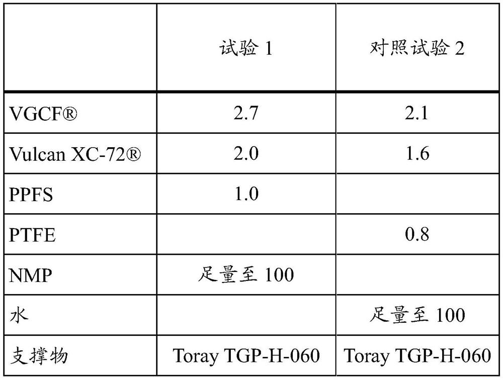
[0100] Dispersions of carbon particles according to the invention and PPFS in NMP (Test 1), and non-inventive dispersions in water with polytetrafluoroethylene (PTFE) instead of PPFS (Comparative Test 2) were prepared as follows:

[0101] carbon black (Vulcan ) and carbon fibers produced in the gas phase mix. The hydrophobic polymer in question is then introduced, followed by the solvent (NMP or water). The mixture was then dispersed in a Dispermat under vacuum (-0.9 bar) at 6000 rpm for 20 minutes to form a dispersion.

[0102] Table 1 below lists the proportions (expressed in mass percent relative to the total mass of the dispersion) used for each dispersion tested and the supports used.

[0103] [Table 1]

[0104]

[0105] The dispersions were deposited on Toray TGP-H-060 supports for Trial 1 and Comparative Trial 2 at ambient temperature using a knife coating bar with a height of 200 μm.

[01...

Embodiment 3

[0110] Characterization of the microporous layer obtained in Example 2

[0111] The surface properties of the microporous layer obtained in Example 2 were evaluated by water droplet deposition. All deposits obtained from the various tests showed a hydrophobic surface. It should be noted that, on the contrary, this property was obtained for Control Experiment 2 only after heat treatment.

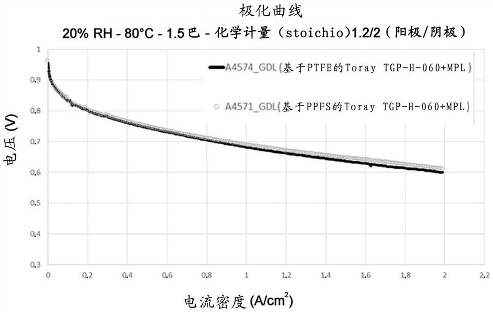
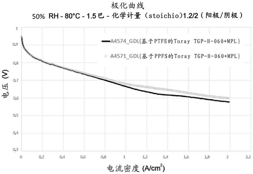
[0112] These various microporous layers formed on carbon supports were used as gas diffusion layers in fuel cells, and the electrochemical performance of the gas diffusion layers was also tested according to the protocol described above in the "Equipment and Technique" section.

[0113] figure 1 and figure 2 The polarization curves measured at 20% and 50% relative humidity for the microporous layer obtained in Example 2 for Test 1 and Control Test 2 are shown, respectively. These two microporous layers on Toray TGP H 060 supports performed similarly, reaching 2A / cm at a voltage of about ...


PUM

PropertyMeasurementUnit
lengthaaaaaaaaaa
thicknessaaaaaaaaaa
thicknessaaaaaaaaaa

Abstract

The invention relates to a method for forming a hydrophobic conductive microporous layer (MPL) at the surface of a support, said method comprising at least the following steps: (a) providing a non-aqueous dispersion of carbon particles, (b) forming a deposit of this dispersion at the surface of the support, (c) drying the deposit formed in step (b) to form said microporous layer, and, if appropriate, (d) washing the microporous layer obtained at the end of step (c), characterised in that the carbon particles are formulated in the dispersion together with at least one polypentafluorostyrene polymer in an organic solvent solution.

Description

technical field [0001] The present invention relates to a method for forming an electrically conductive microporous layer suitable for forming gas diffusion layers of the type used in fuel cells. Background technique [0002] It is recalled that a fuel cell is formed by a single individual cell or by stacking a plurality of individual cells of a fuel cell, the individual cell usually consisting of two electrodes separated by an ion-exchange electrolyte, the assembly clamped between two bipolar plates. These electrodes generally include an active layer filled with a catalyst and is the site for electrochemical reactions, and a gas diffusion layer. The gas diffusion layer is inserted into the active layers (anode, cathode) and serves to distribute reagents (H 2 , air or O 2 ), the gas diffusion layer consists of a porous conductive structure and is usually carbon based. The gas diffusion layer plays multiple roles (mechanical stress, O 2 and H 2 Transport from channel to...

Claims


Application Information

Patent Timeline
Patent Type & Authority Applications(China)
IPC IPC(8): H01M4/88H01M4/86H01M8/1007
CPCH01M4/8807H01M4/8657H01M4/8605H01M8/1007H01M8/0245H01M8/0239H01M8/0234Y02E60/50
Inventor 纪尧姆·奥佐夫弗雷德里克·富达-奥纳纳乔尔·波谢莱昂内尔·皮卡尔
Owner COMMISSARIAT A LENERGIE ATOMIQUE ET AUX ENERGIES ALTERNATIVES
Why Eureka
Try Eureka