LCD unit, LCD apparatus, and method of setting drive voltage of LCD unit

a technology of lcd unit and drive voltage, which is applied in the direction of identification means, instruments, computing, etc., can solve the problems of contrast and color not being uniform on each screen, and achieve the effect of simple operation

Inactive Publication Date: 2014-05-06
YAZAKI CORP
View PDF8 Cites 0 Cited by
  • Summary
  • Abstract
  • Description
  • Claims
  • Application Information

AI Technical Summary

Benefits of technology

[0007]An object of the present invention is to provide an LCD unit, an LCD apparatus, and a method of setting a drive voltage of the LCD unit with a simple operation.
[0012]According to a fourth aspect of the present invention, a method of setting drive voltages of a plurality of LCD units of an in-car display apparatus, includes the steps of: pasting a label on a place of each LCD unit, the each label including an information code, which is information-coded from a data of the drive voltage to achieve the best contrast in optical characteristics of the associated LCD unit (pasting step); grouping the plurality of the LCD units into a plurality of groups based on the best contrast and a transmittance of an OFF segment for optical characteristics of the respective LCD units (grouping step); selecting the plurality of the LCD units in the same group among the plurality of the groups (selecting step); mounting the LCD units selected to the in-car display apparatus (mounting step); reading the data of the drive voltage to achieve the best contrast from the information code included in the each label (reading step); and setting the drive voltage to achieve the best contrast based on the data read (setting step).
[0017]Preferably, the measuring step further comprises the step of measuring a luminance of the ON segment at the best contrast; the pasting step further comprises the step of coding the luminance of the ON segment evaluated at the evaluating step; the reading step further comprises the step of reading the luminance of the ON segment from the information code included in the label of the each LCD unit; and the correcting step further comprises a fixed-valued correction step by reducing the corrected set values of the electronic volumes of the LCD units, which have the luminances of the ON segments equal to or more than the prescribed threshold value compared with the LCD units with lower luminances, by the prescribed fixed value.

Problems solved by technology

When the plurality of the LCD units are operated with a same voltage, the LCD units result in non-uniform appearances on each screen about contrast and color.

Method used


Image

  • LCD unit, LCD apparatus, and method of setting drive voltage of LCD unit
  • LCD unit, LCD apparatus, and method of setting drive voltage of LCD unit
  • LCD unit, LCD apparatus, and method of setting drive voltage of LCD unit

Examples


Embodiment Construction

[0032]An embodiment of the present invention is explained by referring to the drawings.

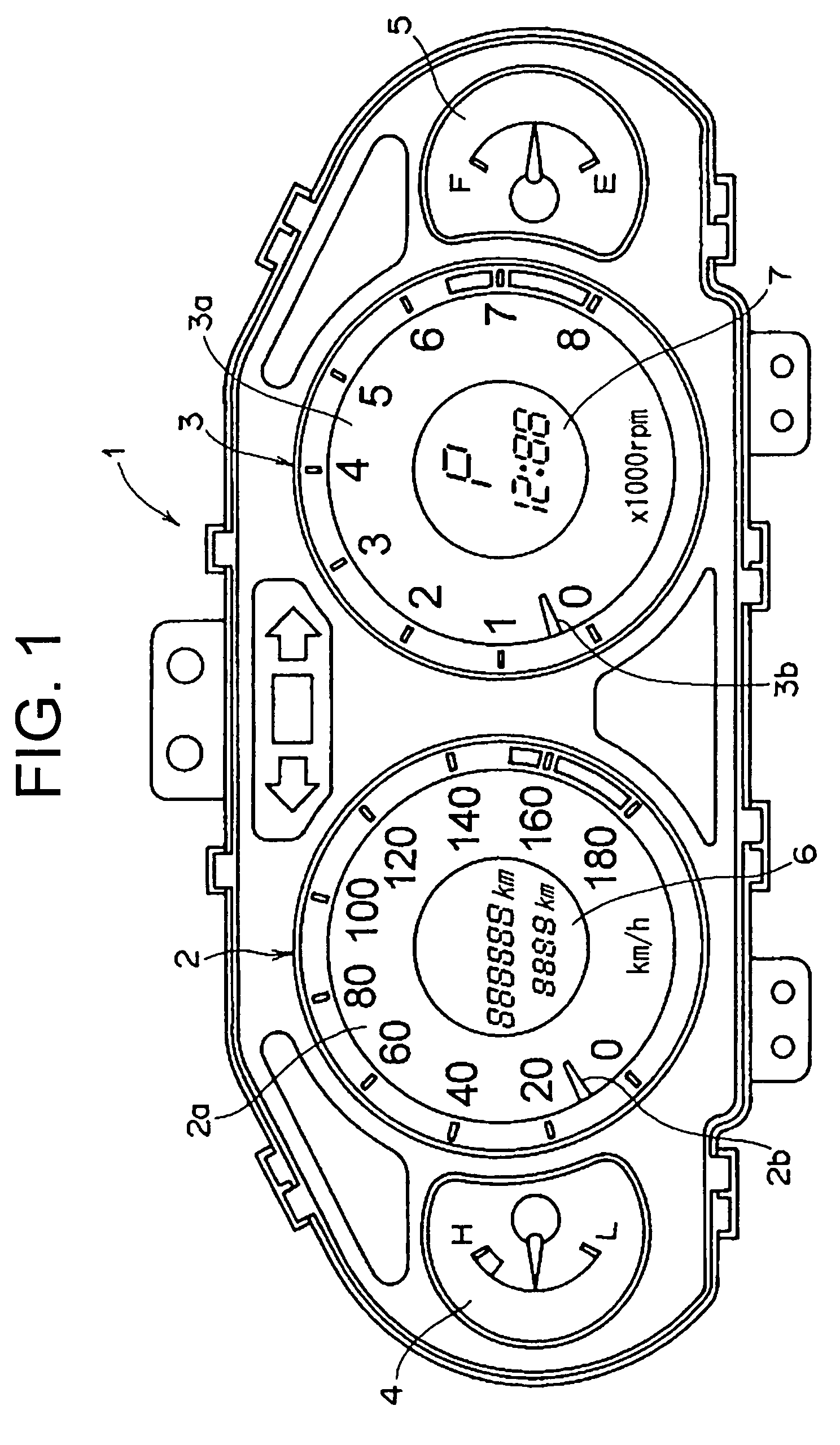
[0033]FIG. 1 is a front view of an in-car display apparatus including LCD apparatuses for which a drive voltage is set. The in-car display apparatus 1 includes a speedometer 2, a tachometer 3, a heat gauge 4, a fuel gauge 5, and two LCD units 6 and 7. The speedometer 2 has an indicator 2b appearing near to a circumference of a dial plate 2a for indicating a numerical scale on the dial plate 2a. The LCD unit 6 is disposed on an opening at the center of the dial plate 2a for displaying a display screen. The tachometer 3 has an indicator 3b appearing near to a circumference of a dial plate 3a for indicating a numerical scale on the dial plate 3a. The LCD unit 7 is disposed on a opening at the center of the dial plate 3a for displaying a display screen.

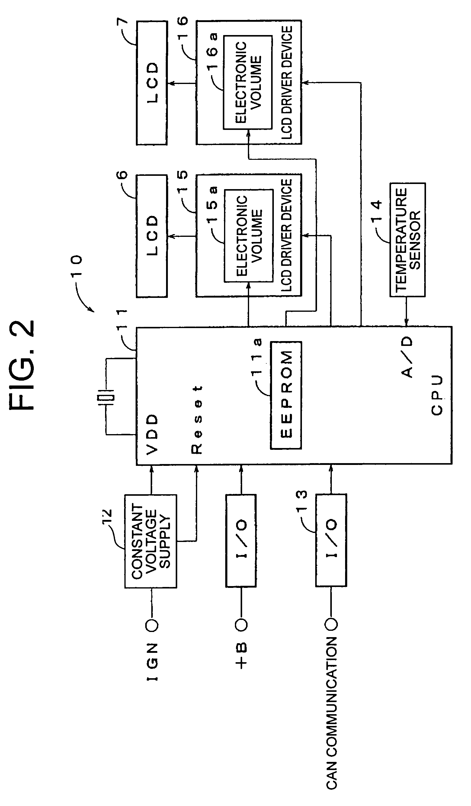
[0034]FIG. 2 shows a block diagram of a drive circuit 10 to drive the LCD units 6 and 7 of the in-car display apparatus 1. The drive circuit 10 include...


PUM


Abstract

The present invention is to provide an LCD unit, an LCD apparatus, and a method of setting a drive voltage of the LCD unit with a simple operation. The LCD unit includes a label pasted on a place of the LCD unit, wherein the label includes an information code, which is information-coded from a data of a drive voltage for achieving the best contrast in optical characteristics of the LCD unit. The best drive voltage to drive the LCD unit with the best contrast is thereby easily set.

Description

BACKGROUND OF THE INVENTION[0001]1. Field of the Invention[0002]The present invention relates to an LCD unit, an LCD apparatus, and a method of setting a drive voltage of the LCD unit.[0003]2. Description of Related Art[0004]An in-car display apparatus utilizing an LCD (Liquid Crystal Display) apparatus is mounted in a motor vehicle, for example JP-2002-36911-A. It is necessary to drive the LCD apparatus with a drive voltage for achieving the best display.[0005]In a conventional method, a data of a drive voltage, which provides the best display or the best contrast, of an LCD apparatus utilized in an in-car display apparatus is manually inputted to a memory device of the in-car display apparatus by means of a setting device or a microcomputer when manufacturing the in-car display apparatus. The drive voltage is usually referred to a specification of the LCD unit.[0006]A plurality of the LCD units utilized in the in-car display apparatus have a variety of the drive voltages for achie...

Claims


Application Information

Patent Timeline
Patent Type & Authority Patents(United States)
IPC IPC(8): G09G3/36
CPCG09G2370/04G09G2320/0666G09G2320/0233G09G3/18G09G2330/028G09G2320/066G06F3/1423G09G2320/02G09G3/001G09G2320/041G09G3/36G02F1/133G09F9/35
Inventor YOSHIMURA, ATSUSHI
Owner YAZAKI CORP
Why Eureka
Try Eureka