Finite state encoders and decoders for vector signaling codes

a vector signaling and encoder technology, applied in the field of communication, can solve problems such as preventing a receiver from understanding exactly, imposing on the signal some unwanted noise and/or timing uncertainty, and introducing such noise or uncertainty

Active Publication Date: 2014-05-06
KANDOU LABS
View PDF7 Cites 146 Cited by
  • Summary
  • Abstract
  • Description
  • Claims
  • Application Information

AI Technical Summary

Benefits of technology

[0050]In some embodiments, the state information is used to enforce transition of state on each transmission wire, thereby relaxing constraints on

Problems solved by technology

The communication environment (referred to herein as the “channel”) may introduce or impose on the signals some unwanted noise and/or timing uncertainty.
The nature of the transmitter and receiver might also introduce such noise or uncertainty.
Thus, in transporting the information from a transmitter to a receiver (or in both directions between two transceivers), there are constraints that might prevent a receiver from understanding exactly what the transmitter sent.
With short periods, this can impose tight constraints on the transmitter.
However, it is typically not a simple matter to just increase bandwidth.
For example, simply changing a period of a transmission, such as by reducing the period, T, in half to double the bandwidth might create other problems.
It also may be that the transmitter and/or receiver cannot keep up (and might also be constrained such that the problem cannot be solved by simply throwing more circuitry at the problem and/or running more in parallel).
However, such operations use power in the transmitter and possibly also in the receiver.
Yet another constraint is pin usage.
Increasing the number of pins can ameliorate constraints on bandwidth and power consumption.
However, this reduces the pin-efficiency (“PE”), which can be a constraint in cases where chip-to-chip communication occurs, as ICs typically have tight constraints and trade-offs a

Method used


Image

  • Finite state encoders and decoders for vector signaling codes
  • Finite state encoders and decoders for vector signaling codes
  • Finite state encoders and decoders for vector signaling codes

Examples


Embodiment Construction

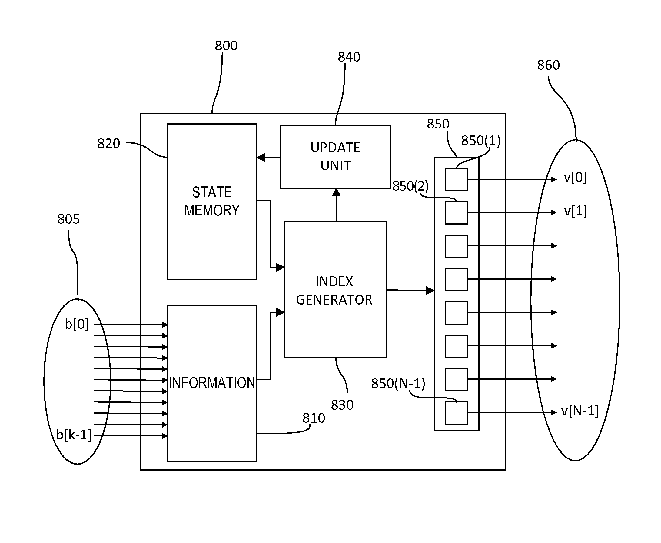
[0078]Various embodiments of communication systems, transmitters, receivers, and methods for transmitting and receiving over various types of channels are described herein. Various examples herein are not meant to be limiting.

[0079]In the typical example, information is represented by physical quantities or values, such as electrical signals, optical signals or radio signals and a transmitter receives that information in electronic or electrical form and generates a signal that it sends to a channel, typically periodically. The channel may introduce or impose on the signals some unwanted noise and / or timing uncertainty. That might cause the receiver to misinterpret the signal.

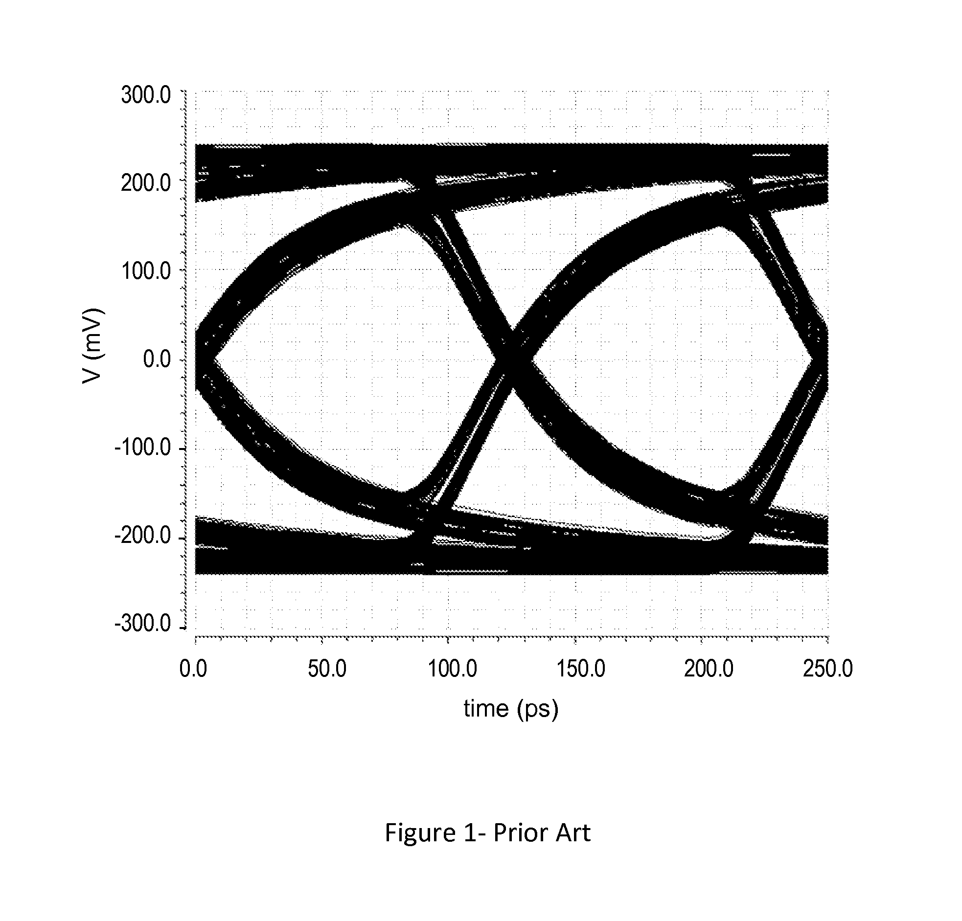
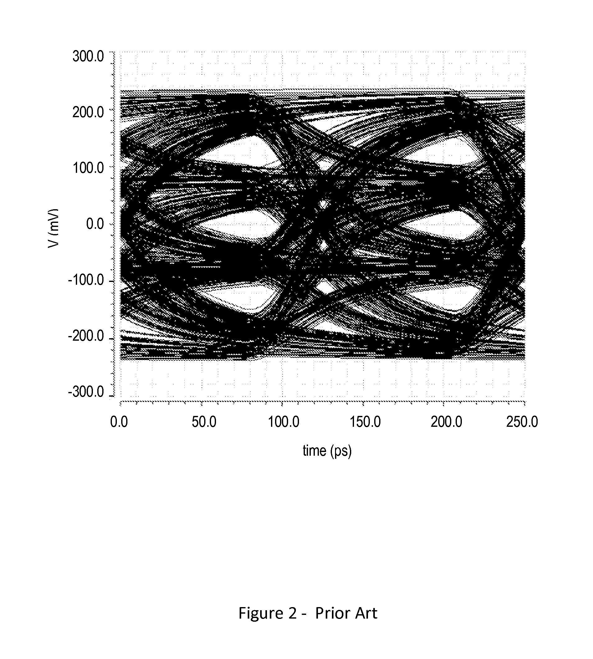
[0080]Eye diagrams represent a received periodic signal where the signal over various periods are overlaid. One measure of performance of a high speed chip-to-chip or device-to-device communication system is the eye-diagram of the received waveforms, possibly after additional processing. The eye diagram corresp...


PUM


Abstract

In a chip-to-chip communication system and apparatus, a set of physical signals to be conveyed over a communication bus is provided, and mapped to a codeword of a vector signaling code using the physical signals and a state information, wherein a codeword is representable as a vector of plurality of real-valued components, and wherein a vector signaling code is a set of codewords in which the components sum to zero and for which there is at least one component and at least three codewords having different values in that component; and wherein the state information is a plurality of information present in continuous or discrete form which may have been obtained from previous codewords transmitted over the communication bus.

Description

CROSS-REFERENCES TO RELATED APPLICATIONS[0001]The following prior applications are herein incorporated by reference in their entirety for all purposes:[0002]U.S. patent application Ser. No. 12 / 784,414, filed May 20, 2010, naming Harm Cronie and Amin Shokrollahi, entitled “Orthogonal Differential Vector Signaling” (hereinafter “Cronie I”).[0003]U.S. patent application Ser. No. 12 / 982,777, filed Dec. 30, 2010, naming Harm Cronie and Amin Shokrollahi, entitled “Power and Pin Efficient Chip-to-Chip Communications with Common-Mode Resilience and SSO Resilience” (hereinafter “Cronie II”).[0004]U.S. patent application Ser. No. 13 / 030,027, filed Feb. 17, 2011, naming Harm Cronie, Amin Shokrollahi and Armin Tajalli entitled “Methods and Systems for Noise Resilient, Pin-Efficient and Low Power Communications with Sparse Signaling Codes” (hereinafter “SPM”).[0005]U.S. patent application Ser. No. 13 / 176,657, filed Jul. 5, 2011, naming Harm Cronie, Amin Shokrollahi entitled “Methods And Systems ...

Claims


Application Information

Patent Timeline
IPC IPC(8): H04L27/00
CPCH04L1/004H04L27/00H04L25/14G06F13/42Y02D10/00
Inventor CRONIE, HARMSHOKROLLAHI, AMIN
Owner KANDOU LABS
Why Eureka
Try Eureka