Sliding stage cementing tool and method

a cementing tool and sliding stage technology, applied in the field of sliding stage cementing tools and methods, can solve the problems of loss in formation, inability to cement the entire well, and inability to achieve single stage cement injection

Active Publication Date: 2014-05-13
SAUDI ARABIAN OIL CO
View PDF25 Cites 15 Cited by
  • Summary
  • Abstract
  • Description
  • Claims
  • Application Information

AI Technical Summary

Problems solved by technology

However, as wells are increasingly being drilled deeper, the hydraulics for cementing the casing wellbore annulus in a substantially deep well makes the single stage cement injection process impracticable.
Also, in some instances it is impossible to cement the entire well.
For example, cement is not provided in portions of the well, where the well formation pressure is less than well hydrostatic pressure, or where the formation is too porous so high cement slurry pressure in the case induces formation breakdown, which leads to losses in the formation, as a result, no cement is present.
However, presently known tools experience failures such as failure to inflate the packer element, failure to open ports, failure to close ports, and disconnection of the tool from the casing string.

Method used


Image

  • Sliding stage cementing tool and method
  • Sliding stage cementing tool and method
  • Sliding stage cementing tool and method

Examples


Embodiment Construction

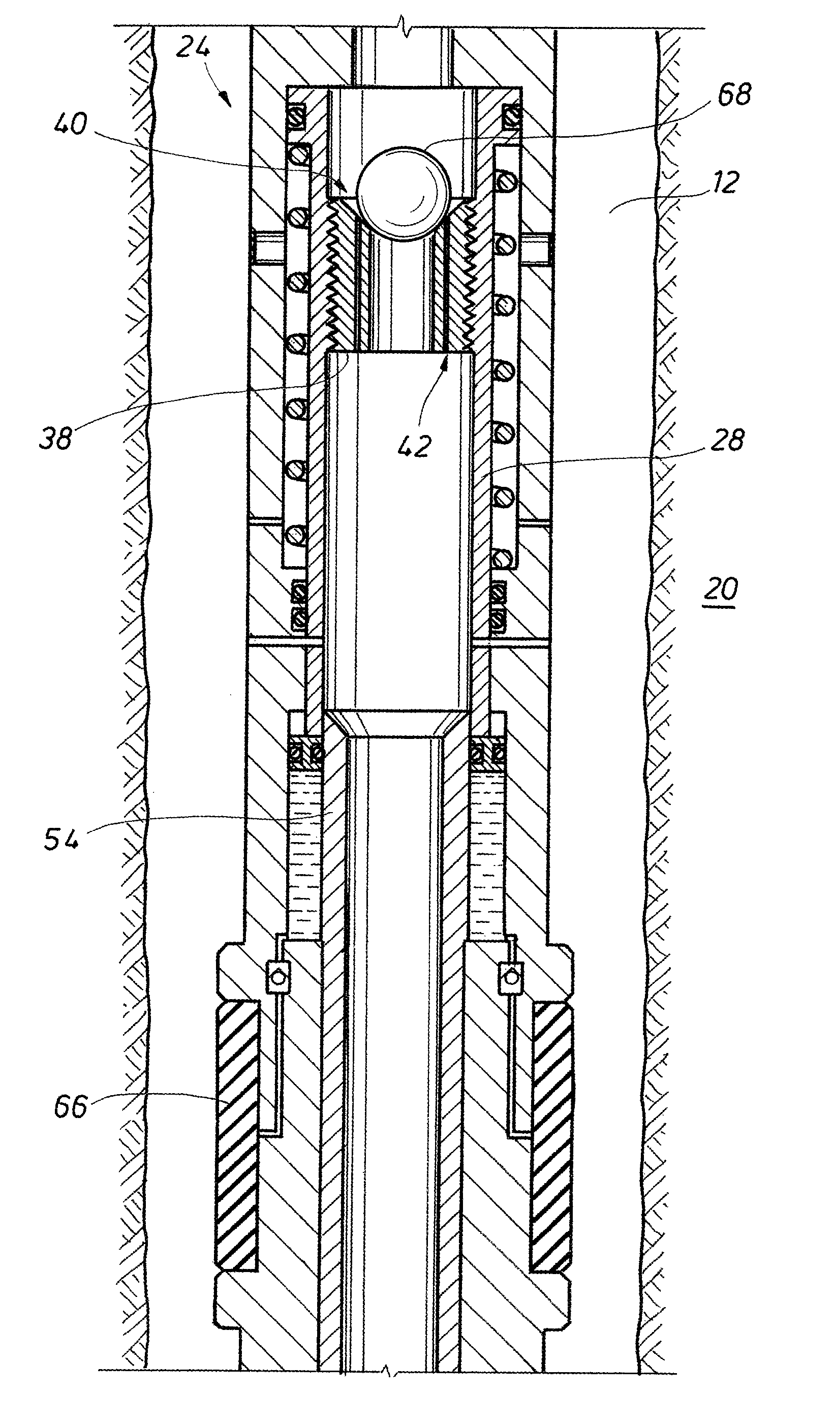
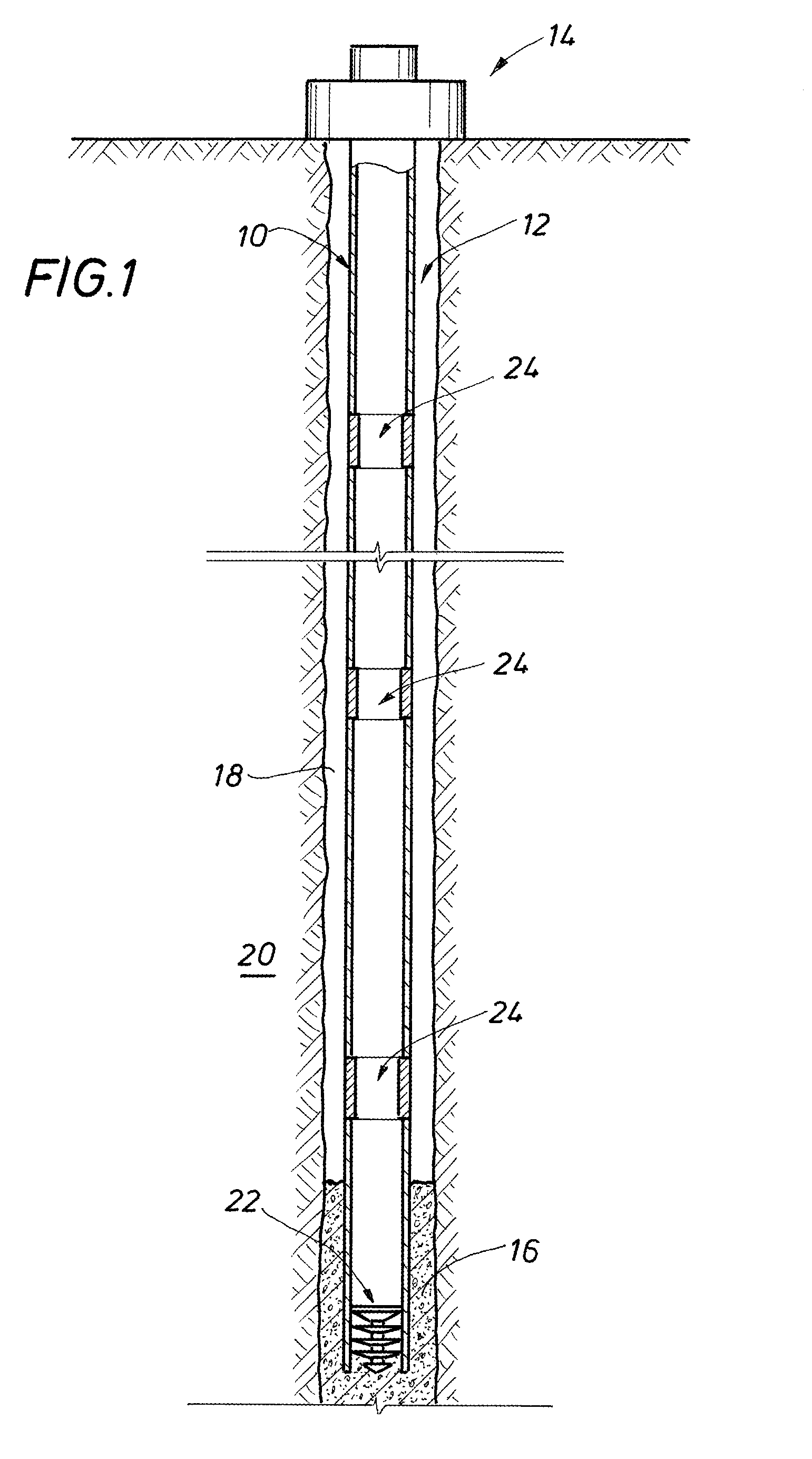
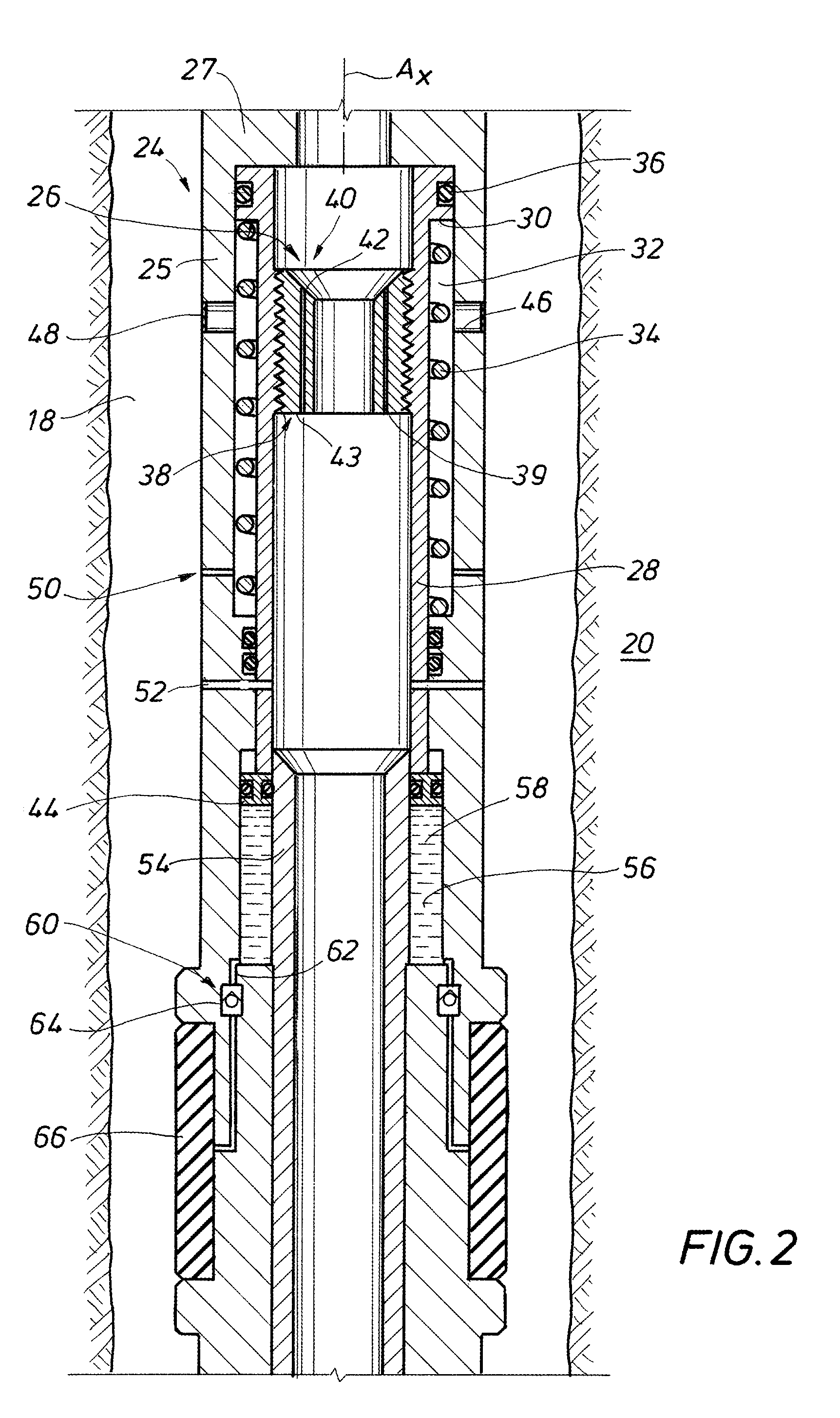
[0017]Shown in side sectional view in FIG. 1 is an example of a string of casing 10 set in a wellbore 12. The casing 10 is shown supported on its upper end by a wellhead assembly 14 disposed at the entrance to the wellbore 12 on the surface. In the embodiment of FIG. 1, cement 16 is shown being inserted into an annulus 18 formed between the casing 10 and walls of the wellbore 12. The cement 16 secures the casing 10 to the formation 20 that circumscribes the wellbore 12. The cement 16 may be injected into the casing 10 via the wellhead assembly 14, a plug 22 can be inserted into the casing 10 above the cement 16. Pressure applied to the upper end of the plug 22 urges the plug and cement 16 through and out of the bottom of the casing 10. After exiting the casing 10, the cement 16 flows into the lower end of the annulus 18 and upwards within the annulus 18. How far up the annulus 18 the cement 16 flows is dictated by the pressure at the bottom end of the casing 10. To overcome the high...


PUM


Abstract

A downhole tool provided within a casing string for use in cement staging operations. The tool includes a sleeve in the tool that selectively slides downward under pressure to expose ports formed in a side wall of the tool. Also, an annulus through the tool is selectively blocked so that cement in the casing string flows radially outward through the ports and into an annulus between the tool and a wellbore. An inflatable packer is included that is integral to the body of the tool and is inflated with a fluid that is pushed into the packer as the sleeve slides downward. An optional expanding agent can be included in the packer that is a metal oxide and is activated with the addition of water.

Description

BACKGROUND OF THE INVENTION[0001]1. Field of the Invention[0002]The present invention relates to an apparatus for use while completing a subterranean hydrocarbon producing well. More specifically, the invention relates to an apparatus for the staging of cement between casing and a wellbore.[0003]2. Description of the Related Art[0004]When completing a subterranean well, casing is typically inserted into the wellbore and secured in place by injecting cement within the casing. The cement is then forced through a lower end of the casing and into an annulus between the casing and wellbore wall. A wiper plug is typically used for pushing the cement from the casing. A displacement fluid, such as water, or an appropriately weighted mud is pumped into the casing above the plug, the pressurized fluid serves as a motive force to urge the plug downward through the casing to extrude the cement from the casing outlet and back up into the annulus. However, as wells are increasingly being drilled ...

Claims


Application Information

Patent Timeline
Patent Type & Authority Patents(United States)
IPC IPC(8): E21B33/13E21B33/127
CPCE21B33/146E21B2034/007E21B21/103E21B2200/06
Inventor ZHOU, SHAOHUA
Owner SAUDI ARABIAN OIL CO
Why Eureka
Try Eureka