System for manufacturing a rough textured molded plastic siding product

a technology of molded plastic siding and manufacturing system, which is applied in the field of system and method of manufacturing molded plastic siding products, can solve the problems of limited embossing system and process, and the roughness of the resulting molded surface can be substantially limited, and achieve the effect of sufficient pliability

Active Publication Date: 2014-05-13
WESTLAKE ROYAL BUILDING PROD INC
View PDF5 Cites 2 Cited by
  • Summary
  • Abstract
  • Description
  • Claims
  • Application Information

AI Technical Summary

Benefits of technology

[0010]The present invention provides a system for manufacturing from heated plastic sheet material a molded siding product having a rough-textured surface, including a rotatable backing roll having a first axis of rotation and an elastically deformable rim defining a circumferential surface, and an embossing element having a moveable embossing surface in compressive engagement with the backing roll, the embossing surface defining a rough-textured pattern. The circumferential surface of the backing roll and the embossing surface define a contact patch therebetween that defines a nip point. The rough-textured pattern is impressed into the circumferential surface of the backing roll, and is capable of being impressed into the circumferential surface of the backing roll in the contact patch through heated plastic sheet material moved through the nip point. A supply of cooling liquid is provided to the nip point, and at least one of the backing roll and the embossing element being cooled thereby. The supply of cooling liquid is sufficient to partially set heated plastic sheet material moved through the nip point and retain therein an impression of the rough-textured pattern and retain sufficient pliability for further plastic forming of the material downstream of the nip point.
[0011]The present invention also provides a method for manufacturing from heated plastic sheet material a molded siding product having a rough-textured surface, the method comprising the steps of: compressively engaging an embossing element having an embossing surface defining a rough-textured pattern, and a backing roll; elastically deflecting a soft rim of the backing roll and forming a contact patch between the embossing element and the backing roll with a nip point between the backing roll and embossing element being defined by the contact patch; directing heated plastic sheet material through the nip point; impressing the rough-textured pattern into the rim of the backing roll in the contact patch through the heated plastic sheet material while moving the material though the nip point; and sufficiently cooling the heated plastic material to partially set the heated plastic sheet material moved through the nip point and retain therein an impression of the rough-textured pattern and retain sufficient pliability for further plastic forming of the material downstream of the nip point.

Problems solved by technology

This is due to limitations of the embossing systems and processes employed in prior systems and methods for manufacturing molded plastic products of this type.
Thus, the roughness of the resulting molded surface can be substantially limited.

Method used


Image

  • System for manufacturing a rough textured molded plastic siding product
  • System for manufacturing a rough textured molded plastic siding product
  • System for manufacturing a rough textured molded plastic siding product

Examples


first embodiment

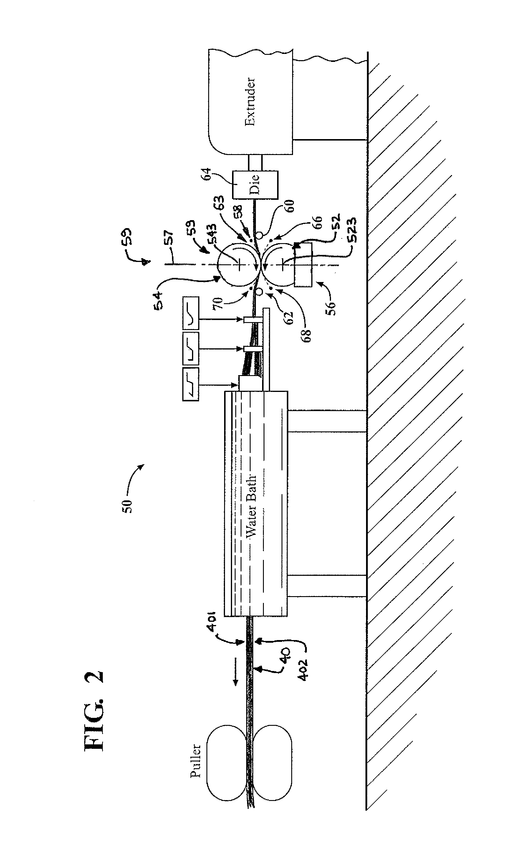
[0024]Referring to FIG. 2, first embodiment manufacturing system 50 for manufacturing a rough-textured molded plastic product, such as lineal 10, includes the schematically shown portion of its extrusion production line. Except as noted herein, system 50 is generally of a known type.

[0025]To achieve the rougher, deeper surface texture of lineal 10, manufacturing system 50 includes an embossing element in the form of embossing roll 52 with a deeper than typical relief texture 521 in its steel circumferential embossing surface 522, and a backing roll 54 having a cylindrical coating or rim 541 formed of a soft rubber, such as silicone, that defines its circumferential surface 542. Coating 541 is elastically deformable and much softer than the typical heat resistant hard rubber typically used in prior backing rolls for vinyl lineal embossing processes, and has a radial thickness of approximately one inch. Rolls 52 and 54 are rotatable about their respective, parallel axes of rotation 52...

second embodiment

[0040]The axial lengths of belt rollers 76, 78, backing roll 80, and guide rollers 60, 62; the distance between belt roller axes 763, 783; and the width and length of belt 74, may all be made sufficiently large to accommodate molding large plastic products such as molded siding panels. Therefore, in addition to molded parts such as transition lineal 10, panels having rough surface textures could also be produced using second embodiment manufacturing system 50a. Multiple such panels, each with different, individual surface textures could also be molded using a single, suitably designed embossing belt 74 of adequate length. So configured, manufacturing system 50a may accommodate, with a single embossing belt 74, the production of a plurality of differently configured siding panels that would reduce the repetition of a common surface texture pattern in a plurality of panels installed on a building.

[0041]Thus, the second embodiment system 50a is capable of molding rough-textured surface...

third embodiment

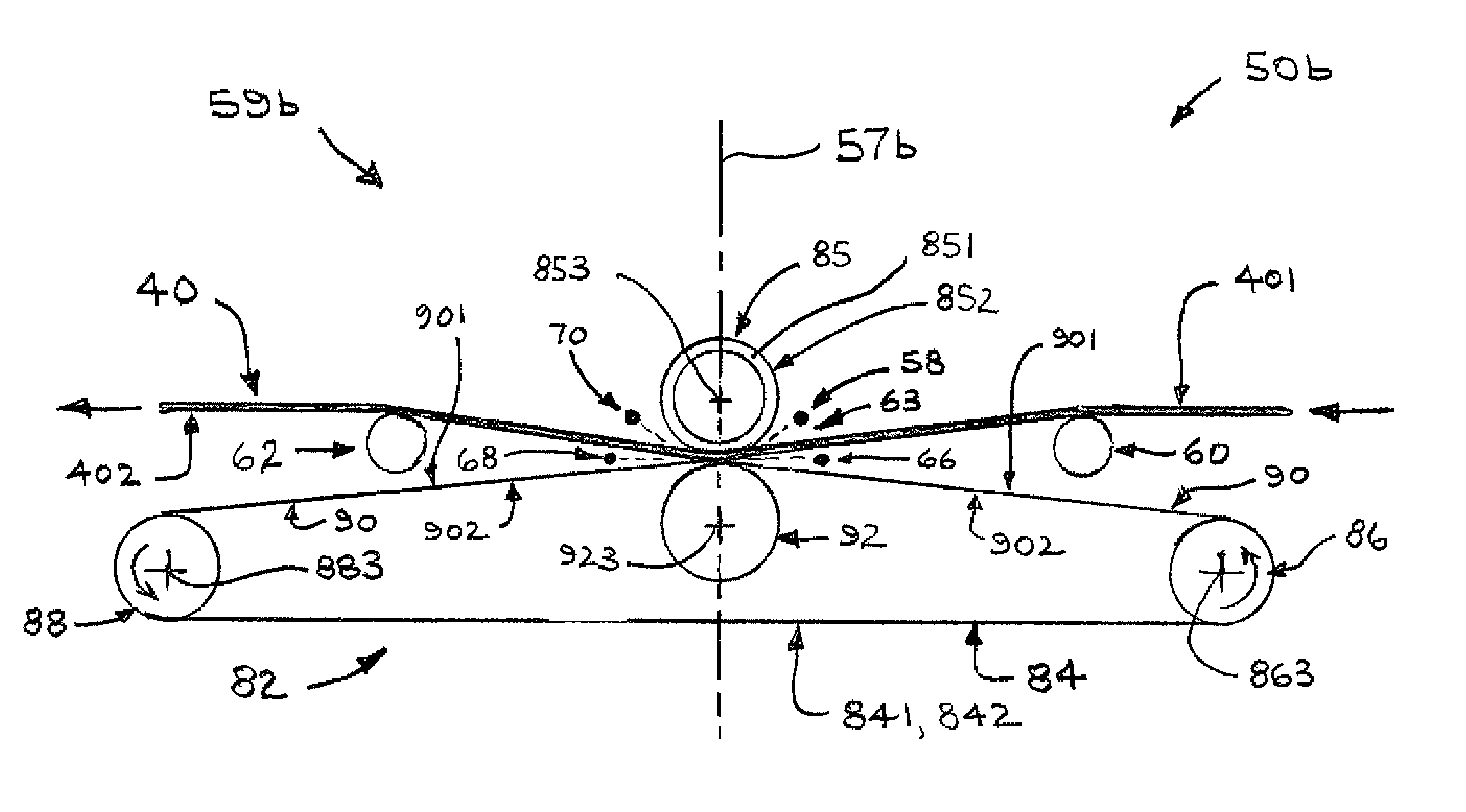
[0044]Thus, in third embodiment system 50b and embossing stand 59b, the soft silicone rubber-rimmed backing roll 85 is positioned above embossing belt assembly 82. Supporting belt upper span 90 against downward movement away from backing roll 85 is belt support roller 92 that bears against the underside 902 of the belt's upper span. Backing roll 85 and the top side 901 of the belt's upper span 90 are in compressed engagement, and bear against each other through the thickness of material 40 in the contact patch.

[0045]Belt support roller 92 has an axis of rotation 923 parallel with axes 863 and 883 of belt rollers 86 and 88, and axis 853 of backing roll 85. Axes 853 and 923 are contained within substantially vertical imaginary plane 57b. The nip point, which in this embodiment is between the outer surface 842 of belt 84 and the circumference 852 of backing roll 85, is defined by a contact patch that is similar to contact patch 551 (FIG. 3), and extends well beyond both sides of imagin...


PUM

PropertyMeasurementUnit
radial thicknessaaaaaaaaaa
compressiveaaaaaaaaaa
shapeaaaaaaaaaa

Abstract

A system for manufacturing from heated plastic sheet material a molded siding product having a rough-textured surface includes a rotatable backing roll having an elastically deformable rim and an embossing element having a moveable embossing surface in compressive engagement with the backing roll. The circumferential surfaces of the backing roll and embossing surface define a contact patch and a nip point. A rough-textured pattern is impressed onto the heated plastic sheet material moved through the nip point. A supply of cooling liquid at least partially sets the heated plastic sheet material to retain an impression of the rough-textured pattern. Respective first and second guide rollers are located higher than the nip point and create a valley defined by the heated plastic sheet material, such that the cooling liquid is collected in a puddle on the heated plastic material proximate the nip point.

Description

RELATED APPLICATIONS[0001]This patent application claims priority to and all advantages of U.S. Provisional Patent Application No. 61 / 366,581, filed on Jul. 22, 2010, of which is hereby incorporated by reference in its entirety.BACKGROUND OF THE INVENTION[0002]a. Field of the Invention[0003]The present invention relates to systems and methods for manufacturing molded plastic members, and particularly molded plastic siding products. As used herein, “molded” refers to any suitable process by which the shape or configuration of the plastic product is formed or altered, including, for example, vacuum forming, injection molding, pressing or stamping, casting, extruding, embossing, etc.[0004]b. Description of the Related Art[0005]It is known to extrude or form a sheet or strip of plastics material such as, for example, a vinyl or other thermoplastic material, and then direct the sheet or strip between a pair of rolls to emboss a pattern or surface texture into at least one surface thereof...

Claims


Application Information

Patent Timeline
Patent Type & Authority Patents(United States)
IPC IPC(8): B29C59/04
CPCB29C2035/1616B29C59/04
Inventor KING, DANIEL, W.
Owner WESTLAKE ROYAL BUILDING PROD INC
Why Eureka
Try Eureka