Fluidized bed drying apparatus

a drying apparatus and flue bed technology, applied in drying machines, lighting and heating apparatus, furnaces, etc., can solve the problems of large amount of energy wasted in the drying of smaller particles and/or dryer particles, and achieve the effect of saving the total energy amount required

Active Publication Date: 2014-05-20
KOREA INST OF ENERGY RES
View PDF0 Cites 0 Cited by
  • Summary
  • Abstract
  • Description
  • Claims
  • Application Information

AI Technical Summary

Benefits of technology

[0007]Embodiments of the invention are proposed to solve the aforementioned drawbacks of the prior art, and one object of the invention relates to providing a fluidized bed drying apparatus wherein gases having different temperature and different flow velocities are supplied to a drying segment through several hot gas supply tubes, saving total energy amount required for drying target-particles for being dried.

Problems solved by technology

Accordingly, a large amount of energy is wasted in the drying of the smaller and / or dryer particles.

Method used


Image

  • Fluidized bed drying apparatus
  • Fluidized bed drying apparatus
  • Fluidized bed drying apparatus

Examples


Embodiment Construction

[0018]The preferred embodiments of a fluidized bed drying apparatus will be described in detail referring to the accompanied drawings. However, it has to be understood that embodiments of the invention are not limited to the preferred embodiments described hereafter.

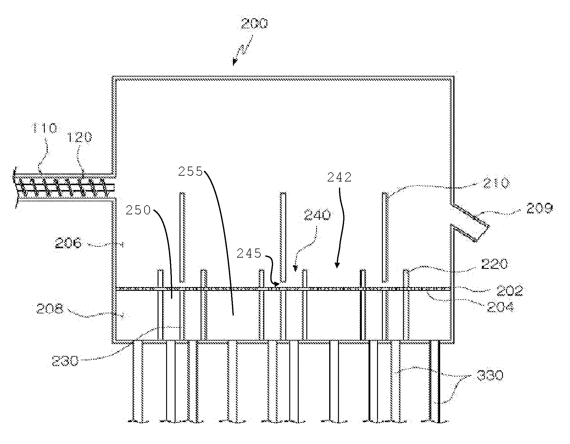
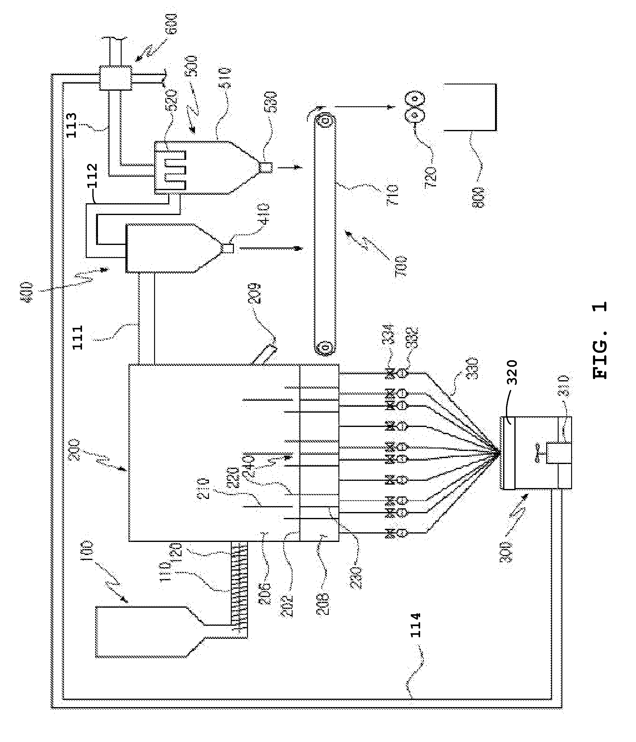
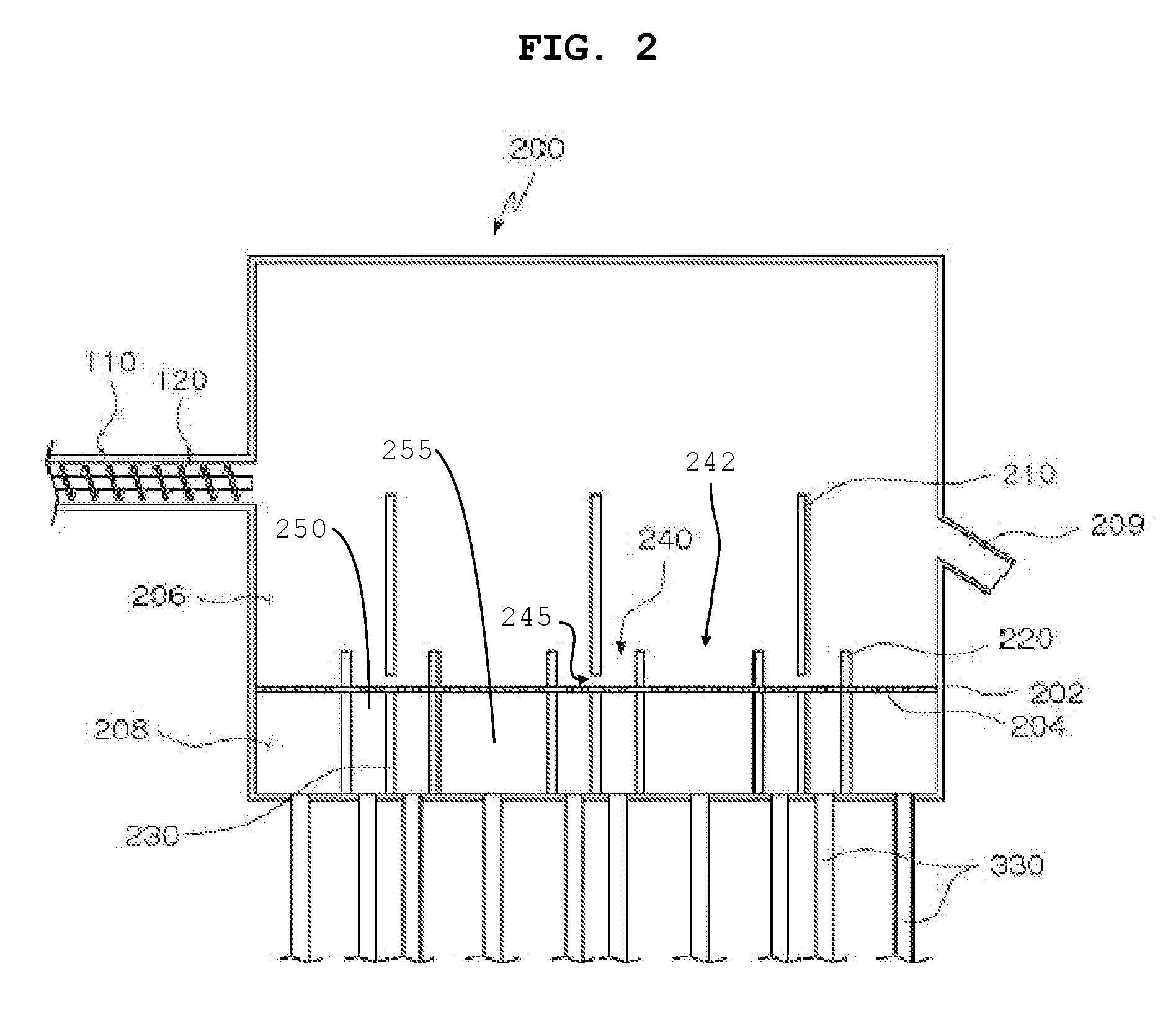
[0019]FIG. 1 is a sectional view of a fluidized bed drying apparatus according to an embodiment of the invention. As shown in FIG. 1, a fluidized bed drying apparatus according to a preferred embodiment of the invention includes: a particle input segment 100 into which wet particles are input; a drying segment 200 for blowing hot gas to efficiently dry the wet particles from the particle input segment; a heated-air flow supplying segment 300 for supplying hot gas to the drying segment 200; a dust collecting segment 400 for collecting powder particles contained in gas being discharged from the drying segment 200; a filtering segment 500 for filtering out powder particles contained in the gas being discharged from the dust...


PUM


Abstract

An apparatus for drying particles in a fluidized state includes a particle input segment into which wet particles are input, a drying segment having a multi-perforated plate dividing an inner space of the drying segment into an upper section and a lower section, a plurality of upper partition plates partitioning the upper section and positioned above the multi-perforated plate, a plurality of lower partition plates in the lower section respectively corresponding to the plurality of upper partition plates, a plurality of pairs of channel plates in the lower section that pass through the multi-perforated plate such that each pair of the plurality of pairs of channel plates are respectively arranged on opposite sides of respective ones of the plurality of upper partition plates and on opposite sides of respective ones of the plurality of lower partition plates; and a heated-air flow supply segment for supplying hot gas to the drying segment.

Description

[0001]This invention claims the benefit of Korean Patent Application No. 10-2009-0095606 filed in Korea on Oct. 8, 2009, which is hereby incorporated by reference in its entirety.BACKGROUND OF THE INVENTION[0002]1. Field of the Invention[0003]Embodiments of the invention relate to a fluidized bed drying apparatus, and more particularly, to a fluidized bed drying apparatus in which target-particles containing moisture, such as brown coal, are exposed to gases having different temperatures and different flow velocities in specified areas of a drying segment to improve drying efficiency.[0004]2. Description for the Related Art[0005]Generally, a fluidized bed drying apparatus has been used for drying efficiently wet particles such as coal, brown coal, slag and limestone, etc., through contact with heated-air over a large area of the particles when the particles are in a state of floating in an upper section of a bed by upward heated-air flow supplied from a lower section of the bed. Tha...

Claims


Application Information

Patent Timeline
Patent Type & Authority Patents(United States)
IPC IPC(8): F26B3/08F26B17/00
CPCF26B3/082F26B3/08F26B21/10F26B21/12F26B17/10
Inventor SHUN, DO WONYI, CHANG KEUNJIN, GYONG TAECHO, SUNG HOPARK, JAE HYEONBAE, DAL HEERYU, HO JUNGPARK, YOUNG CHEOLLEE, SEUNG YONGLEE, SI HYUN
Owner KOREA INST OF ENERGY RES
Why Eureka
Try Eureka