Hold layout device for an aircraft for crew-member rest and aircraft comprising same

a technology for holding layout and aircraft, which is applied in the direction of aircraft accessories, aircraft rest berths, fuselages, etc., can solve the problems of reducing the space that could be made available to passengers and consuming useful space in aircraft, so as to facilitate access to the technical zone, reduce weight and cost of the compartment, and facilitate disassembly or assembly

Inactive Publication Date: 2014-05-20
AIRBUS OPERATIONS (SAS)
View PDF8 Cites 7 Cited by
  • Summary
  • Abstract
  • Description
  • Claims
  • Application Information

AI Technical Summary

Benefits of technology

[0015]According to specific characteristics, at least one said compartment is made up of panels and of a structure supporting the said panels and resting on at least one technical equipment item. By virtue of these arrangements, a special self-supporting structure is avoided and the weight and cost of the compartment are reduced. Moreover, in this way a compartment can occupy an aisle useful only for maintenance or repair operations involving these equipment items. Moreover, each panel thus can be removed independently of the other panels.
[0016]According to specific characteristics, at least one said compartment is made up of panels that can be disassembled or are articulated. By virtue of these arrangements, access to the technical zone is facilitated and / or the commercial zone space easily can be increased. It is noted that the articulated panels are either doors or are articulated on a horizontal axis and that the panels that can be disassembled preferably are equipped with quick fastenings, for example of the “quarter-turn” type. In this way, programmed maintenance-system type access, for example access to the wiring, is facilitated and rapid.

Problems solved by technology

These equipment items, however, consume useful space in the aircraft and reduce the space that could be made available to the passengers.

Method used


Image

  • Hold layout device for an aircraft for crew-member rest and aircraft comprising same
  • Hold layout device for an aircraft for crew-member rest and aircraft comprising same
  • Hold layout device for an aircraft for crew-member rest and aircraft comprising same

Examples


Embodiment Construction

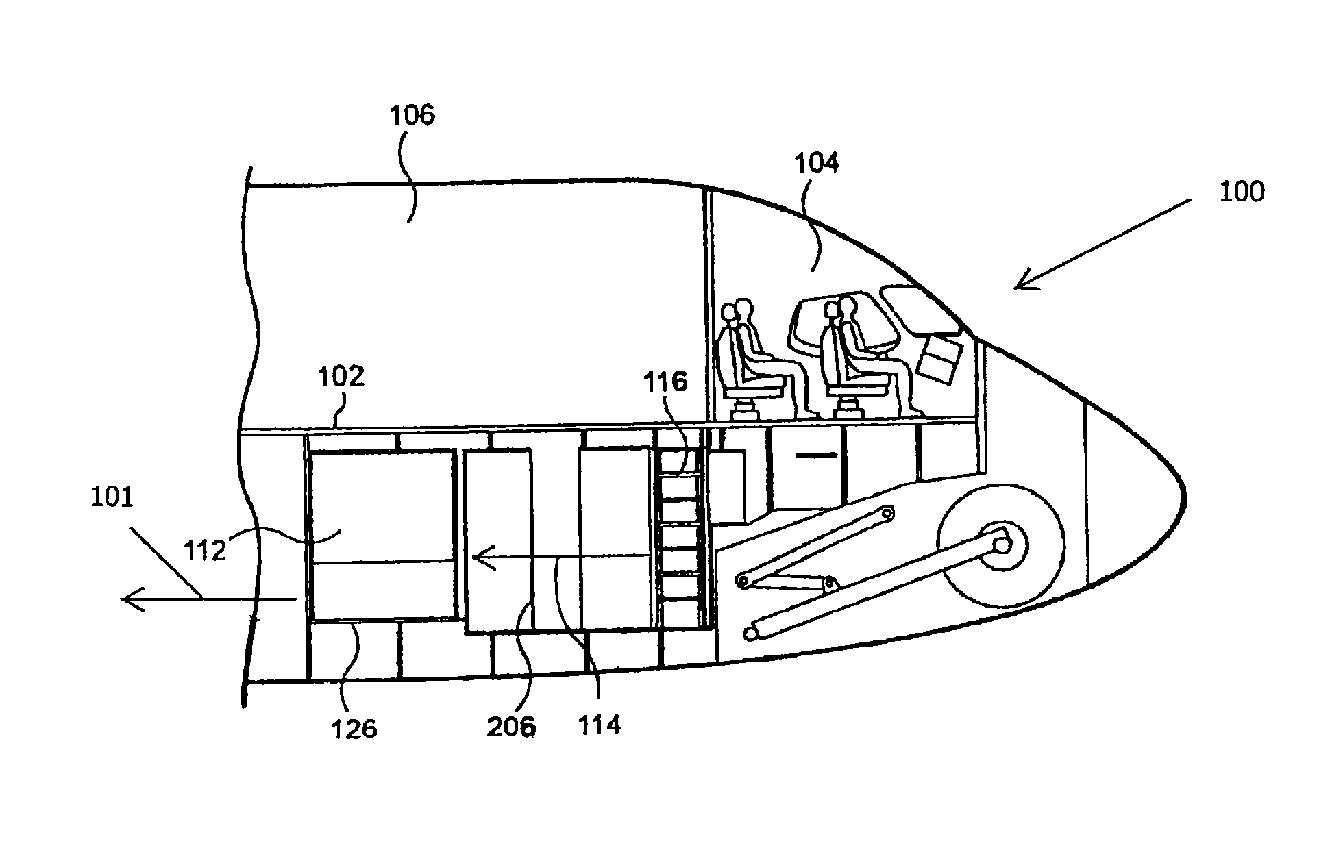
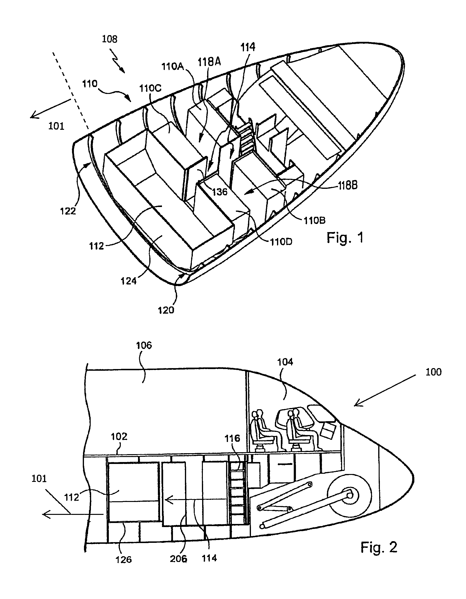
[0049]There is seen, in FIGS. 1 and 2, an aircraft comprising a first zone 101, a floor 102, a floor 102, a cockpit 104, a passenger cabin 106, a hold 108, a technical zone 110 and a rest compartment 112 for crew members.

[0050]Aircraft 100 is of any type. It has a metal fuselage and a metal or carbon structure. Technical zone 110 extends from the nose of the fuselage of the aircraft to below the passenger cabin. Technical zone 110 and compartment 112 are connected, by means of an aisle 114 and stairs 116, to a hatch formed in floor 102 and opening between cockpit 104 and passenger cabin 106.

[0051]In the embodiment described and shown, aisle 114 starts from the stairs and, toward the rear of aircraft 100, first passes, in a portion of the technical zone, between two technical equipment items 110A and 110B, then between two short aisles 118A and 118B orthogonal to aisle 114 and each separating two technical equipment items, respectively 110A and 110C on the one hand, and 110B and 110D...


PUM


Abstract

The invention relates to a device for developing an aircraft hold located under the floor of the passenger cabin and the cockpit and including a so-called commercial area in which freight can be transported and a technical area including technical equipment and located at the front of the commercial area an at least partially under the cockpit, wherein said device includes: at least one compartment sealed relative to the hold located at the front of said commercial area and at the back of a portion at least of the technical area; a staircase connecting each compartment to a portion of the intermediate floor between the passenger cabin and the cockpit; and a sealed corridor extending from said staircase to each of said sealed compartments.

Description

BACKGROUND OF THE INVENTION[0001]This invention relates to a hold layout device for an aircraft for crew-member rest and an aircraft comprising same. It applies, in particular, to the use of the hold to provide a rest, even bedding, area, a cloakroom and / or a baggage bin, for at least one crew member.[0002]In an aircraft, the available space is distributed among the passenger cabin space, the baggage and / or cargo transport hold space, these first two spaces having to be maximized, the cockpit space, and different spaces, for example between the systems cabinets and the portion of the hold able to accommodate standardized containers.[0003]Crew members are asking for an improvement in their comfort and, for the long haul, a rest zone. Moreover, beyond a certain flight duration, the regulations or practices of the airline companies require that a second pilot and copilot pair be present in the aircraft in order to replace the first during the flight. This part of the crew, inactive for...

Claims


Application Information

Patent Timeline
Patent Type & Authority Patents(United States)
IPC IPC(8): B64D47/00B64C1/22B64C1/20
CPCB64D2011/0076B64D11/00Y02T50/46Y02T50/40
Inventor GUERING, BERNARDGUERING, JONATHAN
Owner AIRBUS OPERATIONS (SAS)
Why Eureka
Try Eureka