Annular flange for fastening a rotor or stator element in a turbomachine

a turbomachine and stator element technology, applied in the direction of machines/engines, stators, liquid fuel engines, etc., can solve the problems of limiting the lifetime of the festooned flange, and achieve the effect of simple, effective, and inexpensiv

Active Publication Date: 2014-05-20
SN DETUDE & DE CONSTR DE MOTEURS DAVIATION S N E C M A
View PDF11 Cites 6 Cited by
  • Summary
  • Abstract
  • Description
  • Claims
  • Application Information

AI Technical Summary

Benefits of technology

[0011]A particular object of the invention is to provide a solution to that problem that is simple, inexpensive, and effective.
[0013]Providing bottoms of concave curved shapes instead of flat bottoms on either side of the keying hollow portion and positioning these bottoms of concave curved shapes radially outside (or respectively inside) relative to the flat bottoms of the other hollow portions, enables tangential stresses to be spread over the length of each concave curved bottom.
[0014]The invention thus avoids increasing tangential stresses at the edges of the orifices in the solid portions adjacent to the keying hollow portion and also in the zones connecting said adjacent solid portions to the concave curved hollow portions.

Problems solved by technology

Such an increase in local stress concentration may lead to the formation of cracks in the zones where stresses are concentrated, thereby limiting the lifetime of the festooned flange.

Method used


Image

  • Annular flange for fastening a rotor or stator element in a turbomachine
  • Annular flange for fastening a rotor or stator element in a turbomachine
  • Annular flange for fastening a rotor or stator element in a turbomachine

Examples


Embodiment Construction

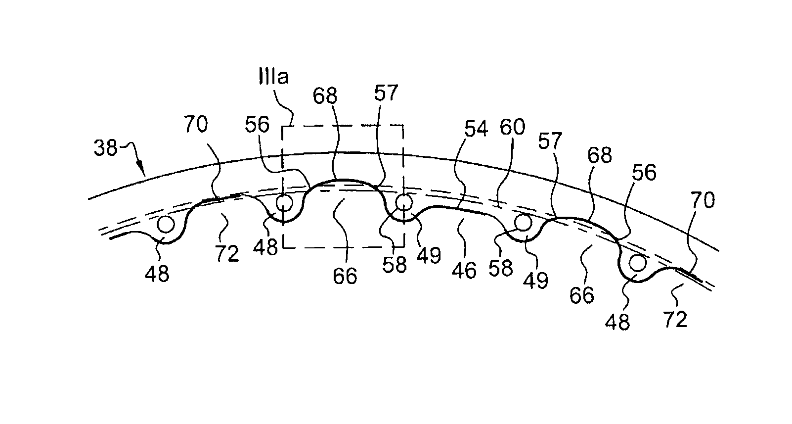
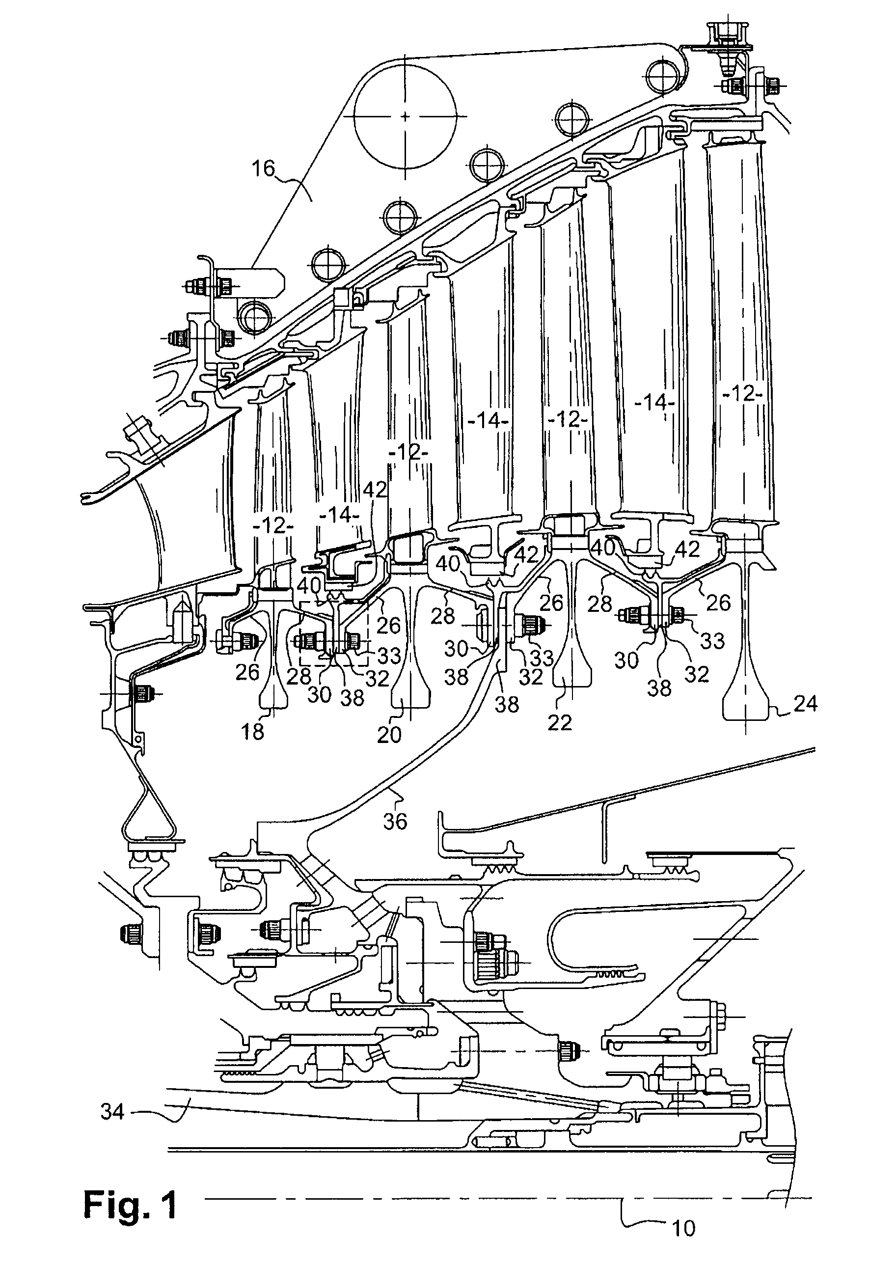
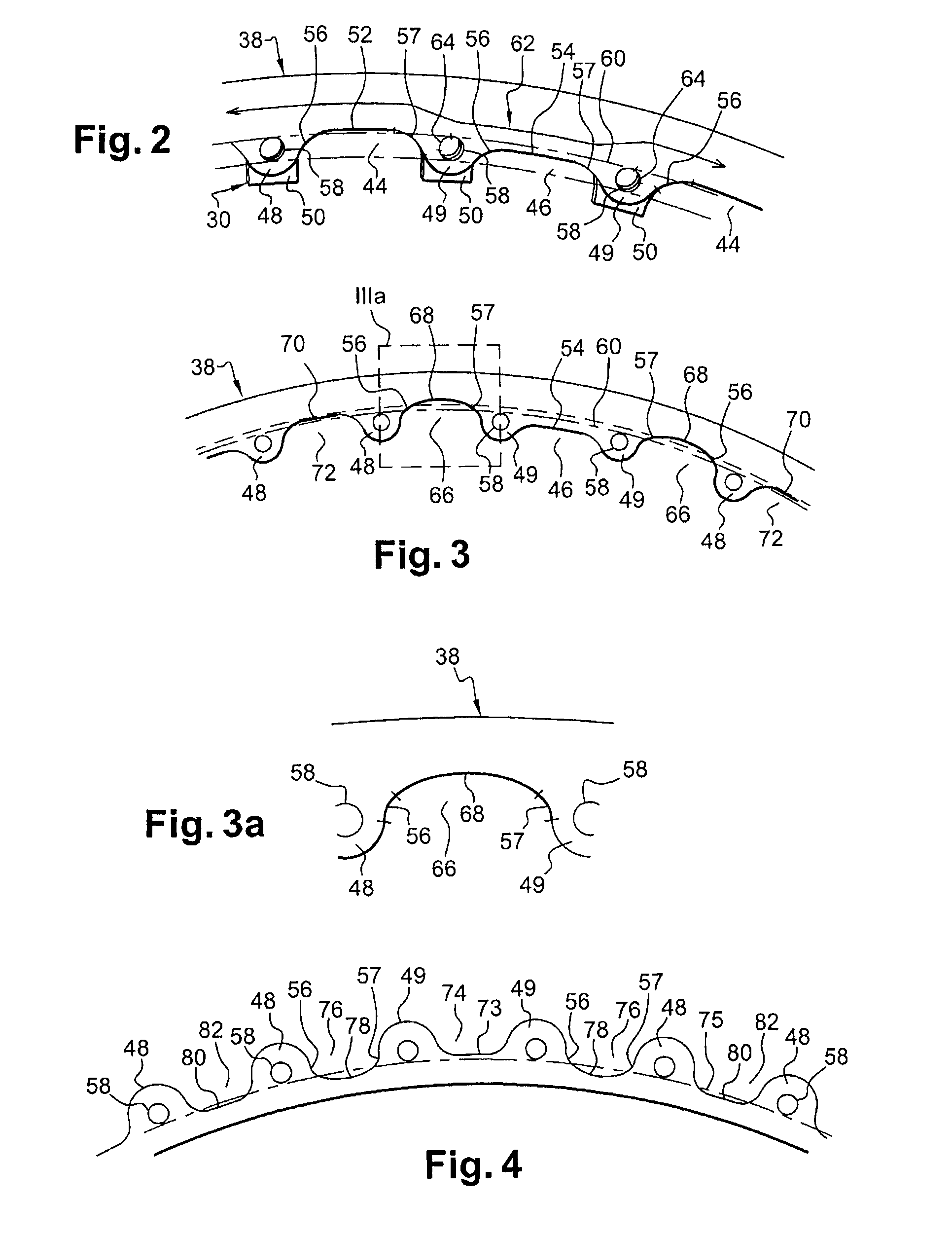
[0027]Reference is made initially to FIG. 1, which shows a low pressure turbine rotor of axis 10 comprising alternating moving blades 12 and stationary vanes 14 housed in an outer casing 16. The radially inner ends of the moving blades 12 are fastened to the outer peripheries of rotor disks 18, 20, 22, 24. Each disk 18, 20, 22, 24 has upstream and downstream frustoconical walls 26 and 28 at its outer periphery connecting with the other disk by means of annular flanges 30, 32 that extend radially inwards and that are fastened to one another by bolts 33. The set of disks is connected to a turbine shaft 34 via a drive cone 36 including an annular flange 38 clamped between the annular flanges 30, 32 of the disks 20 and 22.

[0028]In order to avoid unwanted air flow between the inner periphery of a row of stationary vanes 14 and the downstream and upstream frustoconical walls 28 and 26 of the disks, a radial annular flange 38 carrying a labyrinth seal 40 on its outer periphery is interpose...


PUM


Abstract

A radial annular flange including in inner or outer periphery alternating solid portions including orifices for passing fastener bolts, and hollow portions having bottoms that are substantially flat. The bottom of at least one keying hollow portion is situated radially inside, or outside, respectively, a circle centered on the axis of the flange and externally, or respectively internally, tangential to the orifices. Two hollow portions are situated on either side of the keying hollow portion having bottoms of concave curved shapes situated radially on the outside, or respectively on the inside, relative to the flat bottoms of the other hollow portions.

Description

BACKGROUND OF THE INVENTION[0001]1. Field of the Invention[0002]The invention relates to annular flanges for fastening rotor or stator elements in a turbine, and also to a turbomachine including such a turbine.[0003]2. Description of the Related Art[0004]In a turbomachine the rotor disks (e.g. turbine disks) are connected together by annular flanges at their radially inner peripheries, those flanges pressing against one another and being fastened together by bolting.[0005]Other elements, such as annular supports for labyrinth seals, may also include annular flanges at their inner peripheries, which flanges are clamped between two annular rotor disk flanges and fastened by the same bolts as the rotor disks.[0006]Such annular flanges are generally festooned, i.e. they have alternating solid portions and hollow portions so as to reduce their weight. The holes for passing the fastener bolts are formed through the solid portions.[0007]In order to fasten together a plurality of juxtaposed...

Claims


Application Information

Patent Timeline
Patent Type & Authority Patents(United States)
IPC IPC(8): F01D25/28
CPCF01D25/243F05D2260/30F01D5/066F01D25/246F05D2260/31
Inventor BELMONTE, OLIVIERLANGEVIN, THOMASLE GOFF, STEVAN
Owner SN DETUDE & DE CONSTR DE MOTEURS DAVIATION S N E C M A
Why Eureka
Try Eureka