
Safety needle with collapsible sheath

a safety needle and collapsible technology, applied in the field of safety needles with collapsible sheaths, can solve the problems of accidental needle sticks, health hazards of needle stick injuries that are of greater risk to health care workers, and accidents, and achieve the effect of convenient disengagement and handling

Inactive Publication Date: 2014-05-20
BARD ACCESS SYST
View PDF197 Cites 17 Cited by
  • Summary
  • Abstract
  • Description
  • Claims
  • Application Information

AI Technical Summary

Benefits of technology

The invention is a needle assembly with a pull-out sheath and acap. The sheath is made of a strong film that can be pulled out without breaking. The cap is easily attached to the housing and can be easily disposed of when the needle is removed. The cap has a spring clip with a leaf that can seal off the needle after use, and a rounded end that slides off the needle without scratching it or obstructing its movement. The cap and housing can be easily manipulated to implant the needle in a patient and can be easily disposed of when the needle is removed. The technical effect of this invention is to provide a needle assembly with improved handling and disposal.

Problems solved by technology

Accidental needle stick injuries, unfortunately, are still common in health care workers, such as nurses, physicians, laboratory workers and housekeeping personnel.
The health hazards associated with needle stick injuries are of greater risk for health care workers now than ever before.
Accidental needle sticks often occur when a blood drawer attempts to recap a needle after use or leaves a contaminated needle exposed on work surfaces where the blood drawer or other workers accidentally impale themselves.
It is well known that used hypodermic needles are extremely susceptible to transmitting diseases.
Problems exist, however, in storing the needle for disposal.
Misalignment of the needle with respect to the cap when trying to reinsert the needle therein can cause the hand that holds the cap to be punctured, thereby increasing the likelihood to transmission of a contagious disease.

Method used


Image

  • Safety needle with collapsible sheath
  • Safety needle with collapsible sheath
  • Safety needle with collapsible sheath

Examples


Embodiment Construction

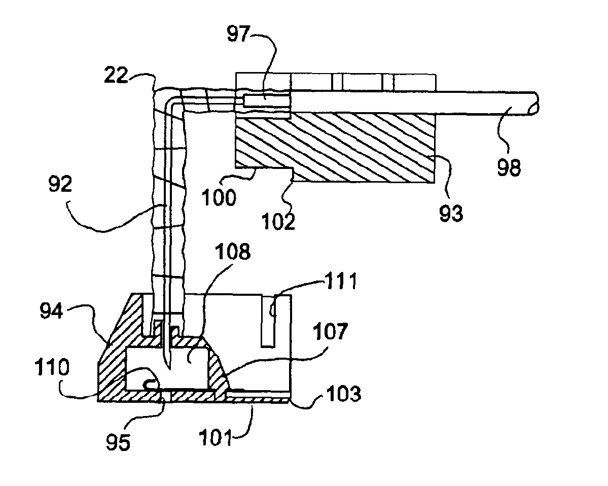
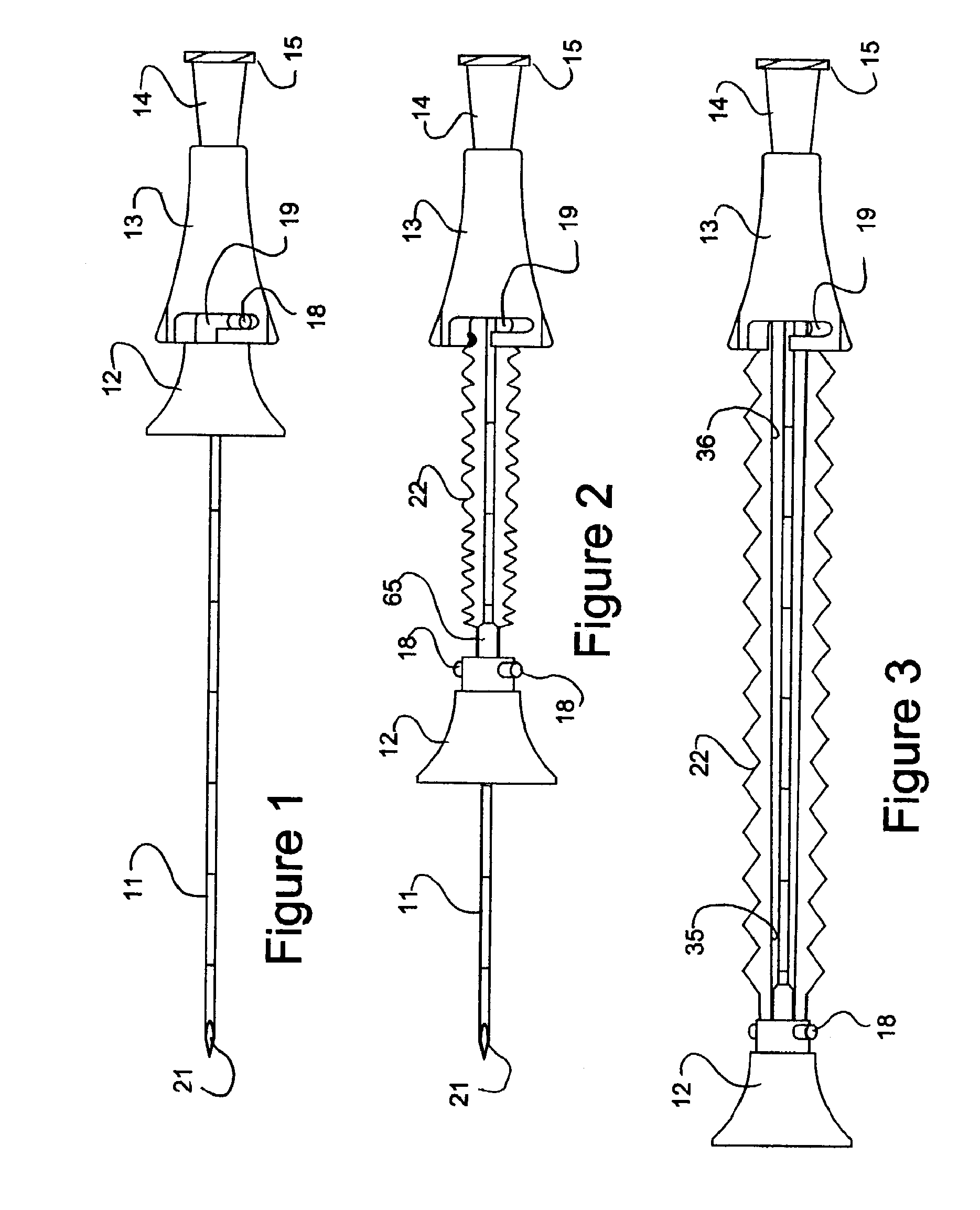
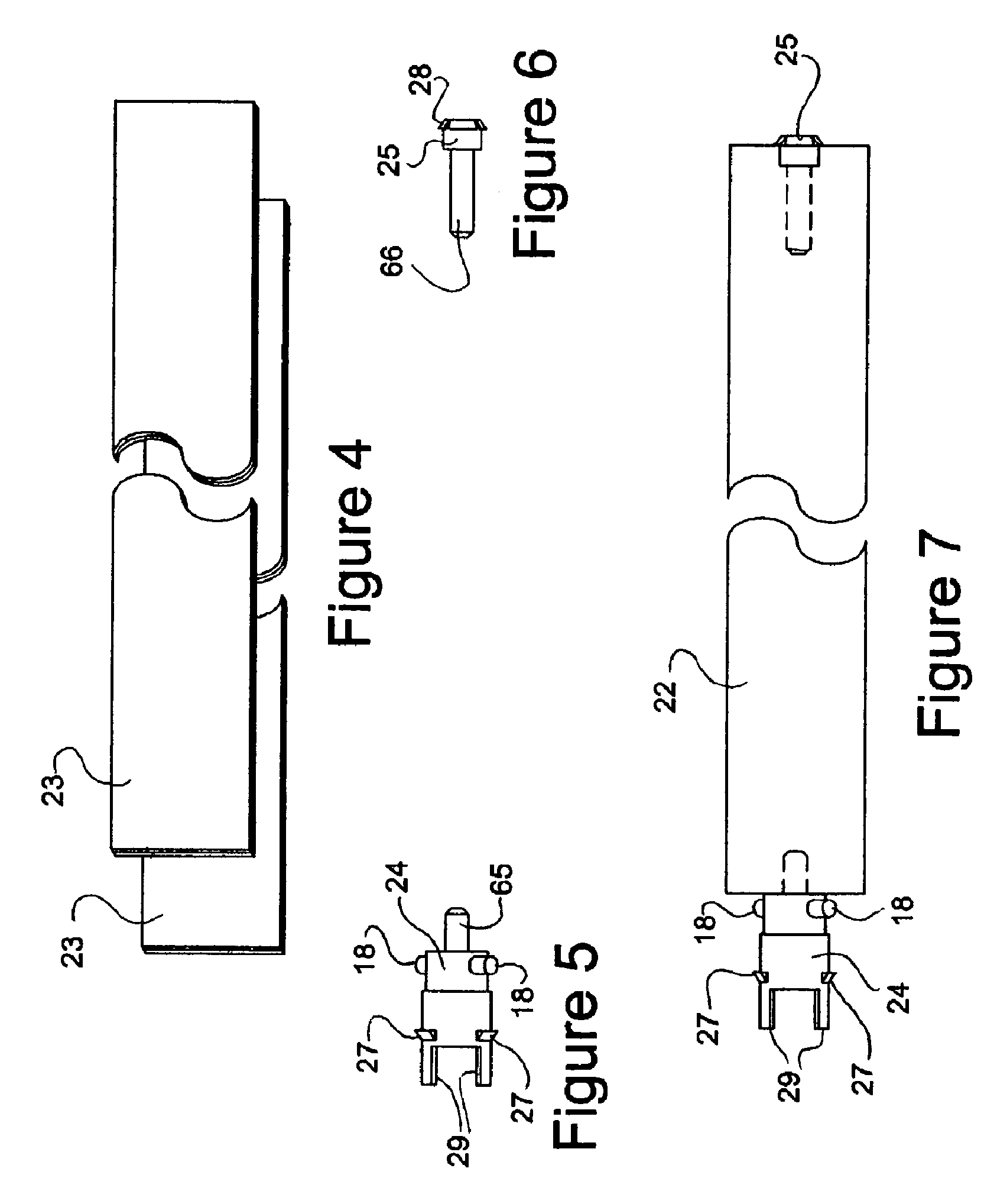
[0075]Referring to FIG. 1, the syringe assembly 10 includes a stainless steel needle 11 having a sharpened end 21 that is mounted in a housing 13 in a conventional manner. In addition, the assembly 10 includes a cap 12 that is concentrically disposed over the needle 11 to be moveable relative to the needle from a first position as indicated in FIG. 1 with the needle extending there through to a second position as indicated in FIG. 3 with an end of the needle 11 disposed therein and sealed relation. In addition, as indicated in FIGS. 2 and 3, a non-resilient tubular sheath 22 is concentrically disposed on an about the needle 11 and is secured to and between the housing 13 and cap 12. The sheath 22 is longitudinally extendable from a collapsed state (not shown in FIG. 1) to an extended state as indicated in FIG. 3 in response to movement of the cap 12 from the first position to the second position thereof.

[0076]Both the cap 12 and housing 13 are made of suitable materials, such as a p...


PUM

PropertyMeasurementUnit
thicknessaaaaaaaaaa
thicknessaaaaaaaaaa
thicknessaaaaaaaaaa

Abstract

A safety needle device includes a housing, a Huber needle, a cap and a sheath. The Huber needle has a first needle leg disposed in the housing and a second needle leg extending perpendicularly of the first needle leg. The cap is disposed over the second needle leg and is movable relative thereto from a first position with the second needle leg extending through the cap to a second position with a tip of the needle disposed in sealed relation in the cap. The sheath is concentrically disposed on and about the needle in a collapsed state, and secured to and between the housing and the cap. The sheath is extendable from the collapsed state to an extended state in response to movement of the cap from the first position to the second position.

Description

PRIORITY[0001]This application is a division of U.S. patent application Ser. No. 10 / 320,168, filed on Dec. 16, 2002, now U.S. Pat. No. 8,066,678, which claims priority of U.S. Provisional Patent Application No. 60 / 339,786, filed Dec. 17, 2001, each of which is incorporated in its entirety into this application.BACKGROUND[0002]This invention relates to a safety needle with a collapsible sheath. More particularly, this invention relates to a safety needle that contains a sharpened edge needle that can be rendered harmless to puncture.[0003]Needle protectors are well known and have been in use for many years with needles used with hypodermic syringes. Conventionally, needles are made with hubs and sockets adapted to be attached to the reduced end of a syringe. A molded plastic cap is conventionally removably secured to the hub of the needle. After mounting the needle on the syringe, the cap is removed to expose the needle for use.[0004]Accidental needle stick injuries, unfortunately, a...

Claims


Application Information

Patent Timeline
Patent Type & Authority Patents(United States)
IPC IPC(8): B29K67/00A61B5/153A61M5/00A61M5/32B29C47/04A61M5/158B29C48/16
CPCB29K2995/0077A61M2005/1581A61M5/3213A61M2005/325A61M2005/3256B29K2067/00B29C47/04A61M5/3243B29C48/16
Inventor VAILLANCOURT, VINCENT L.VAILLANCOURT, MICHAEL J.
Owner BARD ACCESS SYST
Learn More