MEMS actuators with combined force and bi-directional rotation

a technology of combined force and actuator, applied in the field of microelectromechanicalsystem (mems) one-dimensional (tilt) rotation actuator, can solve the problems of increasing complexity and cost, complex fabrication, and increasing the number of cmp steps

Active Publication Date: 2014-05-20
ADRIATIC RES INST
View PDF19 Cites 46 Cited by
  • Summary
  • Abstract
  • Description
  • Claims
  • Application Information

AI Technical Summary

Problems solved by technology

However, the additional deposition and CMP steps significantly increase complexity and cost.
In all cases, complex fabrication has been required, and relatively low frequencies have been achieved due to the gimbals' slow outer axis.
In applications where high speed static scanning is required the previous methods do not provide adequate solutions.

Method used


Image

  • MEMS actuators with combined force and bi-directional rotation
  • MEMS actuators with combined force and bi-directional rotation
  • MEMS actuators with combined force and bi-directional rotation

Examples


Embodiment Construction

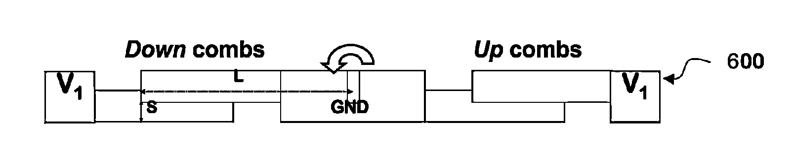
[0041]The rotator as illustrated in FIG. 7 has Upper comb fingers illustrated in dark gray (702&704) at a higher out of plane position than Lower comb fingers illustrated by light gray (703&705). Controlling the rotator voltage V0 (connected to anchor 706& stage 708) and fixed combs' voltage V1 (connected to electrode 707), exerts electrostatic forces between comb fingers 702 and 703 and between comb fingers 704 and 705 that tends to move drive beam 710 and load 701 up (out of plane of the schematic) from its resting neutral position. Only rotation in this ‘up’ direction is possible with this arrangement in a quasi-static sense (due to applied voltage.) Rotator 708 is tethered to anchors 706 via torsion springs 709 which allows the rotator to rotate along axis-1, but constrains the rotator from lateral or vertical translation and rotation in all other directions. This was shown in the cross-sectional schematic of a vertical combdrive actuator 610 in FIG. 6A. The same torsion springs...


PUM


Abstract

A MEMS system comprises a first rotational actuator having a first drive mechanism configured to drive rotation of a first rotator about a first axis, a second rotational actuator having a second drive mechanism configured to drive rotation of a second rotator about a second axis, first and second flexible linkages, a first drive beam coupled to the first rotator and to the first flexible linkage, a second drive beam coupled to the second rotator and to the second flexible linkage, and one or more device mounts coupled to the first and second flexible linkages. The one or more device mounts are configured to provide distributed points of attachment of a device. The rotation of the first and second rotators causes the device mount to rotate or piston.

Description

CROSS-REFERENCE TO RELATED APPLICATION[0001]This application is a continuation-in-part of and claims the priority benefit of prior U.S. patent application Ser. No. 11 / 938,197, filed Nov. 9, 2007, now U.S. Pat. No. 8,043,513, the entire contents of which are incorporated herein by reference. U.S. patent application Ser. No. 11 / 938,197 is a division of and claims the priority benefit of prior U.S. patent application Ser. No. 11 / 003,271 filed Dec. 2, 2004, now U.S. Pat. No. 7,295,726, the entire disclosures of which are incorporated herein by reference. U.S. patent application Ser. No. 11 / 003,271 is a nonprovisional of and claims the benefit of prior U.S. provisional application No. 60 / 526,510 filed Dec. 2, 2003, the entire disclosures of which are incorporated herein by reference. This application is also a nonprovisional of and claims the priority benefit of prior U.S. provisional patent application No. 61 / 179,334 filed May 18, 2009, the entire disclosures of which are incorporated h...

Claims


Application Information

Patent Timeline
Patent Type & Authority Patents(United States)
IPC IPC(8): H02N1/00H02N1/04
CPCB81B3/0062G02B26/0841G02B7/1821B81B2203/058B81B2201/033B81B2203/0118
Inventor MILANOVIC, VELJKO
Owner ADRIATIC RES INST
Why Eureka
Try Eureka