Current source inverter and method for controlling current source inverter

a current source inverter and current source technology, applied in the direction of electric variable regulation, process and machine control, instruments, etc., can solve the problems of destroying elements, destroying elements, achieving zcs and zvs, etc., and achieve the effect of preventing a switching loss

Active Publication Date: 2014-05-20
KYOSAN ELECTRIC MFG CO LTD
View PDF7 Cites 10 Cited by
  • Summary
  • Abstract
  • Description
  • Claims
  • Application Information

AI Technical Summary

Benefits of technology

[0054]As described above, according to the current source inverter and the method for controlling the current source inverter of the present invention, it is possible to prevent a switching loss by a normal switching operation for the commutation operation, without requiring any particular additional control, in the control of the switching elements of the current source inverter.

Problems solved by technology

This current source inverter has a problem that when all the switching elements break the passage of electric current, there is a possibility that current from the DC reactor applies overvoltage on the switching elements and causes element destruction.
There is another problem that at the time of commutation, current and voltage are generated on the switching elements, and this may cause the element destruction.
Therefore, they do not achieve ZCS and ZVS at the time of commutation, and a switching loss occurs.
In addition, surge voltage is generated, and this may cause damage on the switching element.
Since the resonant circuit has a configuration where the resonant capacitor is connected in parallel to the switching element, there is a problem that the capacitor increases in volume.

Method used


Image

  • Current source inverter and method for controlling current source inverter
  • Current source inverter and method for controlling current source inverter
  • Current source inverter and method for controlling current source inverter

Examples


Embodiment Construction

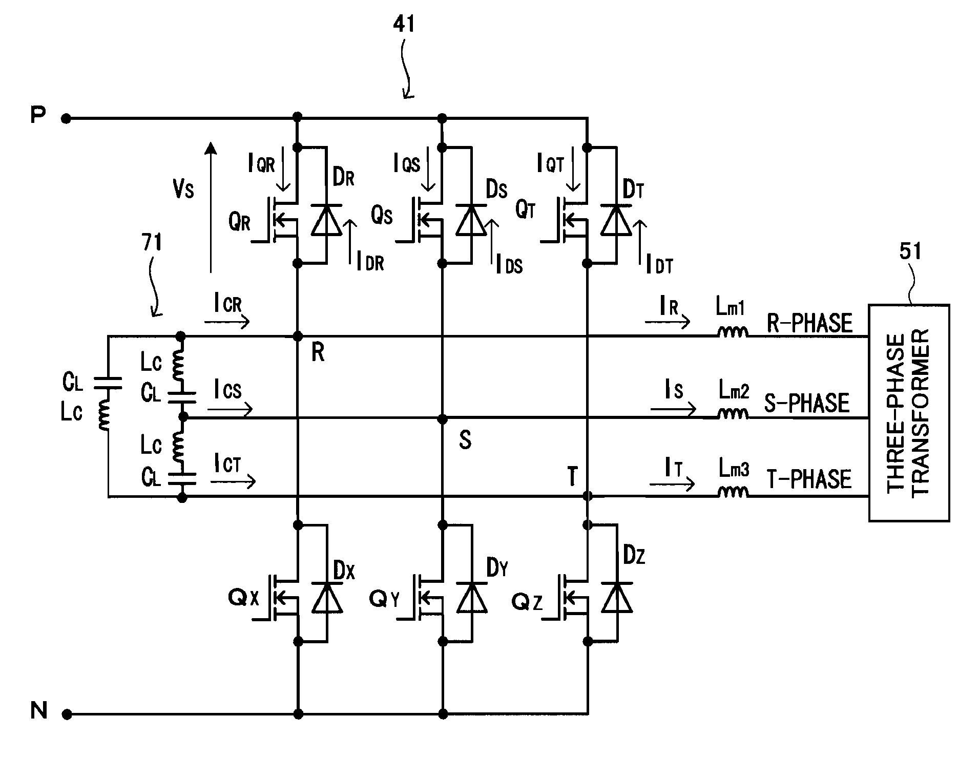
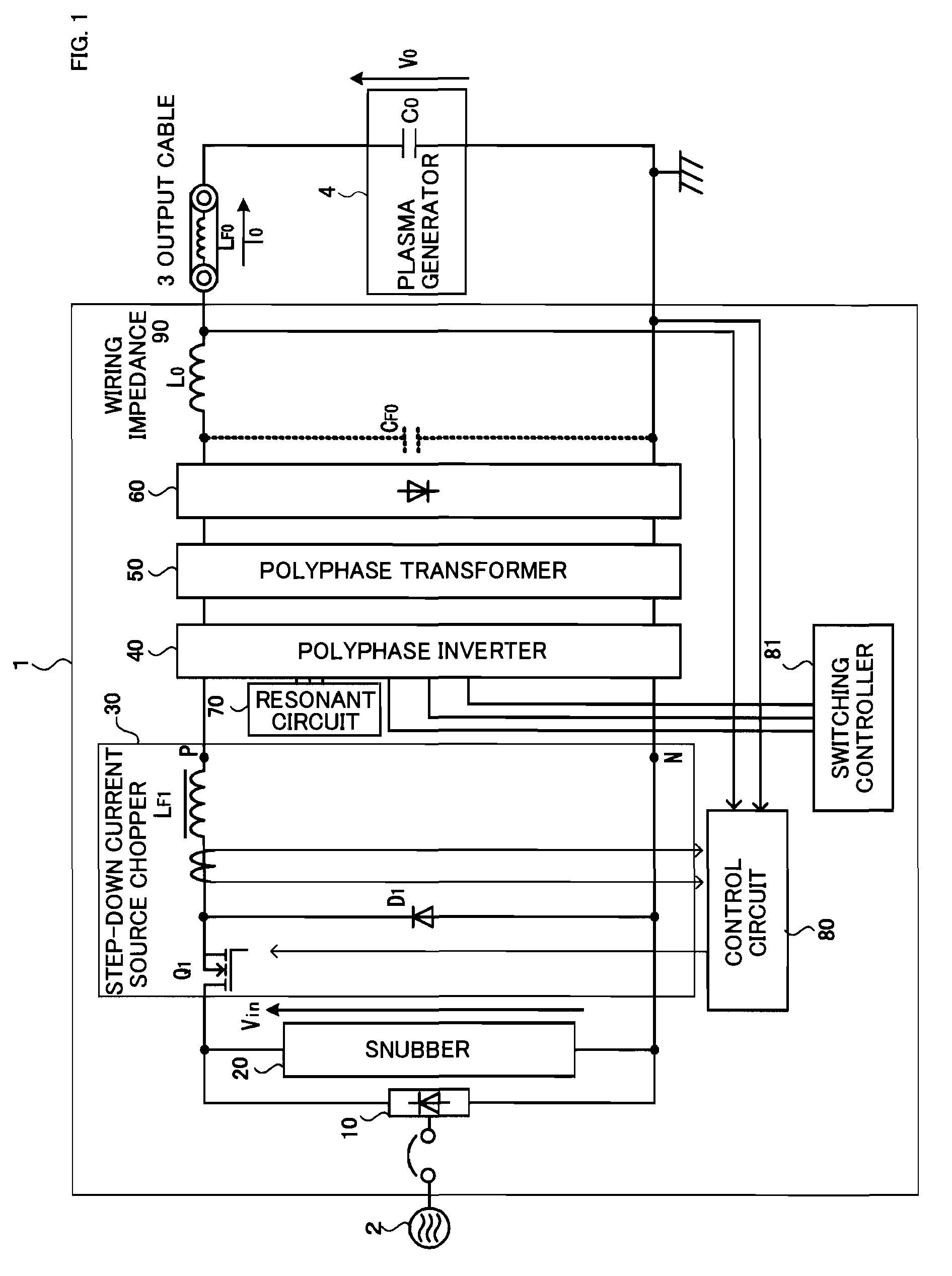
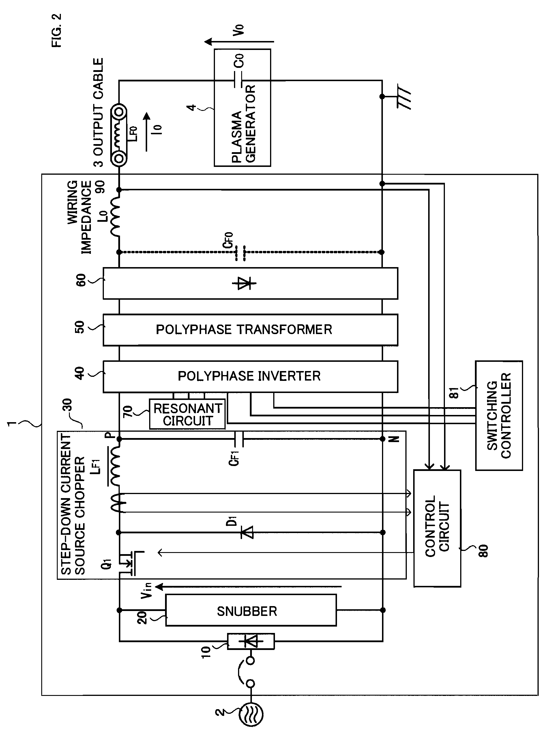
[0072]Hereinafter, embodiments of the present invention will be explained in detail with reference to the accompanying drawings. In the following, for explaining the current source inverter and the method for controlling the current source inverter according to the present invention, FIG. 1 and FIG. 2 are used to illustrate the configuration example of the current source inverter, and FIG. 3 and FIG. 4 are used to illustrate the control example of the current source inverter. With reference to FIG. 5 to FIG. 13, the inverter circuit and the resonant circuit according to the present invention will be explained. Here, a three-phase inverter is illustrated as an example of the multiphase inverter.

[Configuration Example of the Current Source Inverter]

[0073]Firstly, with reference to FIG. 1 and FIG. 2, a configuration example of the current source inverter according to the present invention will be explained.

[0074]The current source inverter 1 of the present invention as shown FIG. 1 is ...


PUM


Abstract

In controlling switching elements of a current source inverter, a switching loss in the switching element is prevented according to a normal switching operation for a commutation operation, without requiring any particular control.In the commutation operation of the current source inverter, a timing for driving the switching elements is controlled in such a manner that an overlap period is generated, during when both a switching element at the commutation source and a switching element at the commutation target are set to be the ON state, a resonant circuit is controlled based on the control of the switching elements having this overlap period, and resonant current of the resonant circuit reduces the switching loss upon commutation operation of the switching elements. By controlling the generation of the resonant current of the resonant circuit by using the control of the switching elements having the overlap period, the resonant current generated by this control renders current and voltage of the switching element at the commutation source to zero when commutation is performed, thereby reducing the switching loss in the commutation operation.

Description

TECHNICAL FIELD[0001]The present invention relates to a current source inverter for supplying current to a load such as a plasma load, for example, and a method for controlling the current source inverter.BACKGROUND ART[0002]A current source inverter is provided with a DC reactor connected to a DC source, a converter for converting DC power from the DC reactor into AC power, and a controller for performing a drive control of switching elements in the converter, and this current source inverter is characterized in that it operates on reducing fluctuations of load impedance caused by a load short or the like, since the inverter is allowed to be treated as a current source when viewed from the load side. By way of example, in the case of plasma load, the inverter operates to maintain the plasma.[0003]The current source inverter has such an advantage as supplying current stably to the load, even when the load fluctuates as described above, it is suitable for supplying power to the plasm...

Claims


Application Information

Patent Timeline
Patent Type & Authority Patents(United States)
IPC IPC(8): H02M3/335H02H7/122H02M7/217H02M7/5387
CPCH02M3/33569H02M7/48H02M2007/4815Y02B70/1491Y02B70/1441Y02B70/10H02M7/4815H02M3/33573H02M3/33571H02M3/01H02M7/44H02M7/42H02M1/084
Inventor YUZURIHARA, ITSUOADACHI, TOSHIYUKIKODAMA, SHINICHI
Owner KYOSAN ELECTRIC MFG CO LTD
Why Eureka
Try Eureka