
AC/AC injection type inductance coupling type wireless energy transmission apparatus

A wireless energy transmission and coupling technology, applied in the direction of output power conversion devices, circuit devices, high-efficiency power electronic conversion, etc., can solve the problems of increased system volume and cost burden, high volume and power level, and reduced system reliability. , to achieve the effect of improving wireless energy transmission efficiency, reducing system cost, and increasing reliability

Inactive Publication Date: 2016-06-01
北京动力京工科技有限公司 +1
View PDF4 Cites 5 Cited by
  • Summary
  • Abstract
  • Description
  • Claims
  • Application Information

AI Technical Summary

Problems solved by technology

However, since the frequency of power frequency alternating current is low, and the voltage amplitude is usually greater than 220V, the volume and power level of the semiconductor devices and energy storage components used in the rectification and filtering module will be relatively high, which will not only add a lot to the system Volume and cost burden, but also prone to electromagnetic interference, reducing system reliability
In addition, the power factor of traditional uncontrolled rectification is low, and two stages of rectification and inverter need to work in series, so the efficiency is low

Method used


Image

  • AC/AC injection type inductance coupling type wireless energy transmission apparatus
  • AC/AC injection type inductance coupling type wireless energy transmission apparatus
  • AC/AC injection type inductance coupling type wireless energy transmission apparatus

Examples


Embodiment

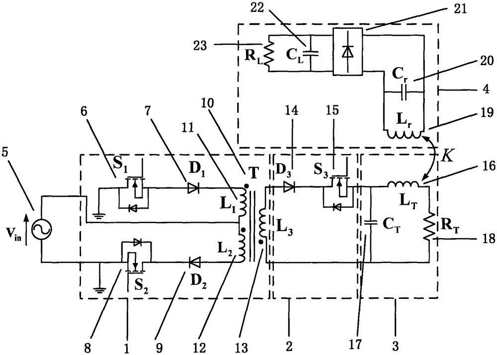
[0037] An AC / AC injection-type inductively coupled wireless energy transmission device, characterized in that it includes a bidirectional flyback energy storage unit 1, an energy transfer unit 2, a high-frequency resonance transmitting unit 3, and a receiving-end resonance unit 4;

[0038] The bidirectional flyback energy storage unit 1 includes a bidirectional switch branch, a transformer T10, and a primary coil L of the transformer T10 1 11 and primary side coil L 2 12 are respectively connected in series with the two branches of the bidirectional switch branch;

[0039] The energy transfer unit 2 is located between the bidirectional flyback energy storage unit 1 and the high-frequency resonance transmitting unit 3;

[0040] The AC power supply 5 provides injected energy to the bidirectional flyback energy storage unit 1, the bidirectional flyback energy storage unit 1 is connected to the energy transfer unit 2, and then connected to the high-frequency resonance transmittin...


PUM


Abstract

The invention discloses an AC / AC injection type inductance coupling type wireless energy transmission apparatus. The apparatus comprises a bidirectional flyback energy storage unit, an energy transfer unit, a high frequency resonance emission unit and a receiving end resonance unit, wherein the energy transfer unit enables the bidirectional flyback energy storage unit and the high frequency resonance emission unit not to intervene each other; the pulse type energy injection at the emission end of the apparatus is controlled to enable the apparatus to transmit energy to the receiving end at a switching frequency that is far below the resonance frequency; the switch loss caused by an overhigh operating frequency of the switch tube is avoided; the wireless energy transmission efficiency of the apparatus is improved; due to the operating characteristics of the bidirectional flyback converter, the apparatus can directly perform energy collection on the alternating current input voltage to realize an AC-to-AC emission end energy transfer process; the volume and the cost of the apparatus are optimized, and the reliability of the apparatus is improved, so that the apparatus has actual practical value; and meanwhile, a first-level AC / AC converter is adopted, so that unity power factor correction can be realized, the cost can be lowered, and the system efficiency is improved.

Description

technical field [0001] The invention relates to an AC / AC injection type inductively coupled wireless energy transmission device, which belongs to the technical field of wireless energy transmission. Background technique [0002] In the inductively coupled wireless energy transfer system, the transmitter inverter is responsible for generating the high-frequency alternating current required in the resonant network coil. In order to meet the high-frequency current requirements of the resonant network, the operating frequency of the switching tube in the inverter generally needs to The resonant frequency is the same, but as the operating frequency increases, the switching loss of the switching tube will lead to a decrease in the overall transmission efficiency. For this reason, some researchers have proposed a discrete injection-type transmitter control method, that is, to keep the input voltage constant and control the intermittent operation of the inverter, so that the resonan...

Claims


Application Information

Patent Timeline
IPC IPC(8): H02J50/12H02M1/42
CPCH02M1/4208Y02B70/10
Inventor 冬雷鞠兴龙王亚楠
Owner 北京动力京工科技有限公司
Learn More