
Control of long-stator linear motor coils of long-stator linear motor stator

A coil and stator technology is applied in the field of controlling multiple LLM coils of the LLM stator, which can solve the problems of high cost and large circuit technology cost.

Active Publication Date: 2017-12-05
B&R IND AUTOMATION GMBH
View PDF5 Cites 5 Cited by
  • Summary
  • Abstract
  • Description
  • Claims
  • Application Information

AI Technical Summary

Problems solved by technology

This results in high costs for the necessarily high number of LLM coils of the LLM stator as well as a high circuit-technical outlay due to the high number of switches

Method used


Image

  • Control of long-stator linear motor coils of long-stator linear motor stator
  • Control of long-stator linear motor coils of long-stator linear motor stator
  • Control of long-stator linear motor coils of long-stator linear motor stator

Examples


Embodiment Construction

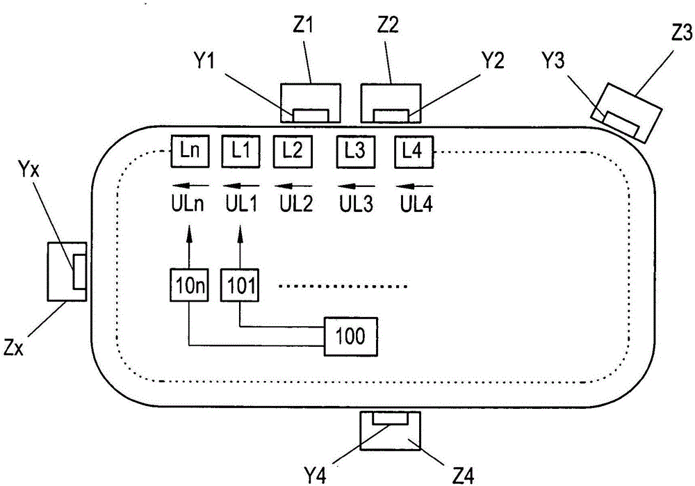
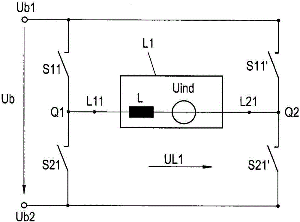
[0027]Figure 1 exemplarily shows a conveyor in the form of a long stator linear motor (LLM). The conveying device here consists of only one conveying section, although in practice a plurality of conveying sections are possible which are combined to form the conveying device, which may also not be formed in a closed track. The conveying device is embodied as an LLM, in which the conveying sections are each formed as part of a long stator of the LLM in a manner known per se. In this case, the transfer section can be further divided in a known manner, for example into several individual transfer sections in the form of a coil arrangement with a plurality of LLM coils. Along the conveying section, therefore, in the longitudinal direction, a plurality of electric LLM coils L1,...,Ln are arranged in a known manner, which LLM coils are connected to the field magnets Y1 on the conveying units Z1...Zx , ..., Yn cooperate. In a likewise known manner, the coil voltages UL1 , . . . , UL...


PUM


Abstract

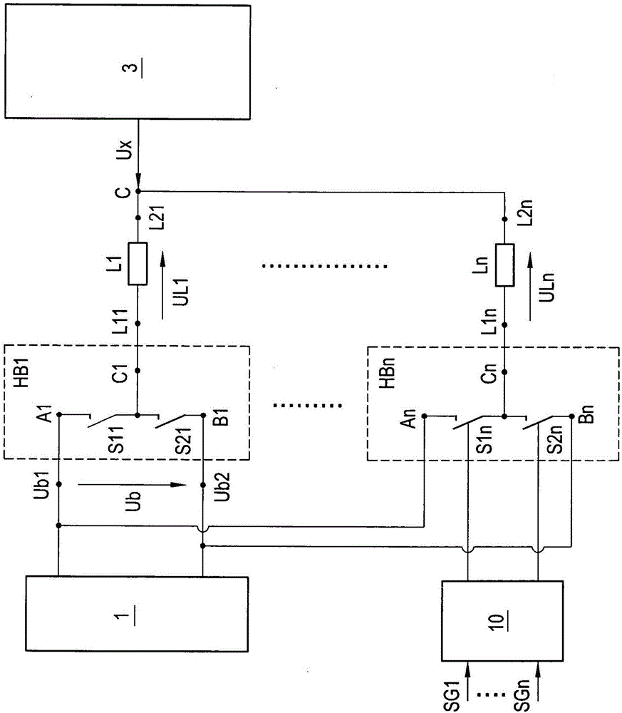
The present invention provides a method and device for controlling the n LLM coils (L1, . . . Ln) of an LLM stator making it possible to change the polarity of the coil voltage (UL1, . . . , ULn) of the n LLM coils (L1, . . . Ln) more easily and with little circuit complexity. It is proposed to apply a first operating potential (Ub1) to n first input terminals (A1, . . . , An) of n half bridges (HB1, . . . , HBn), and apply a second operating potential (Ub2) to n second input terminals (B1, . . . , Bn) of the n half bridges. For each half bridge (HB1, . . . HBn), a first switch (S11, . . . , S1n) is connected between a center point (C1, . . . , Cn) of the respective half bridge (HB1, . . . , HBn) and the first input terminal (A1, . . . , An), and a second switch (S21, . . . , S2n) is connected between the center point (C1, . . . , Cn) of the relevant half bridge (HB1, . . . , HBn) and the second input terminal (B1, . . . , Bn). The center point (C1, . . . , Cn) of the n half bridges is connected in each case to n first terminals (L11, . . . , L1n) of the n LLM coils (L1, . . . , Ln), and the second terminals (L11, . . . , L1n) of the n LLM coils (L1, . . . , Ln) are connected in a control point (C) that is regulated to a predetermined potential (Ux).

Description

technical field [0001] The invention relates to a method and a device for controlling a plurality of LLM coils of an LLM stator. Background technique [0002] The stator of a long stator linear motor (LLM) consists of a plurality of LLM coils arranged side by side, which together form the stator of the LLM. The LLM coils are controlled individually or in groups, wherein it is often also desirable or necessary to change the polarity, ie to change the current direction of the LLM coils, during operation of long-stator linear motors. By controlling the LLM coils, a moving magnetic field is generated which cooperates with an exciter magnet (usually a permanent magnet) on the transfer unit of the LLM to move the transfer unit along the stator. Here, the basic structure and function of the LLM are sufficiently known and therefore not described in detail here. In order to energize the LLM coil to generate a magnetic field, an operating voltage may be provided between a first oper...

Claims


Application Information

Patent Timeline
Patent Type & Authority Applications(China)
IPC IPC(8): H02P25/06
CPCH02P6/28H02P7/02H02M3/156H02P7/292H02M7/219G05F1/575H02P25/06H02P5/74H02P6/006H02M1/0043H02P25/064
Inventor L·法尚C·克拉普奥夫
Owner B&R IND AUTOMATION GMBH
Learn More